Comander Perimeter Security System
Engineering and Installation Manual
Page 5 of 72
1 System Design and Architecture
A Comander system can vary in size from a single standalone Comander Rack to a
network of up to 20 Rack units. The number of Comanders you need depends on the
number of Interceptor cables and other alarm circuits you need, and how far apart they
are physically located.
1.1 The Comander Unit
1.1.1 What is a Comander?
A Comander unit normally consists of at least two units – a Comander Rack and an
optional Marshalling Box.
The Marshalling Box provides robust surge and lightning protection for the Rack's
Interceptor Cable and Monitored Contact inputs, so Rack units which do not require
Interceptor or Contact inputs can operate without an associated Marshalling Box.
Each Rack can support up to 24 Interceptor cable inputs and up to 96 Monitored
Contact inputs. A standard Marshalling Box contains 24 Interceptor inputs and 24
Monitored Contact inputs, but other Marshalling Box configurations are available for
situations where more Contacts are required. The standard Marshalling Box is
connected to the Comander Rack using three cables – two multipair cables each carry
12 Interceptor signals, and a smaller cable with a 9-pin D connector carries the
Monitored Contact signals.
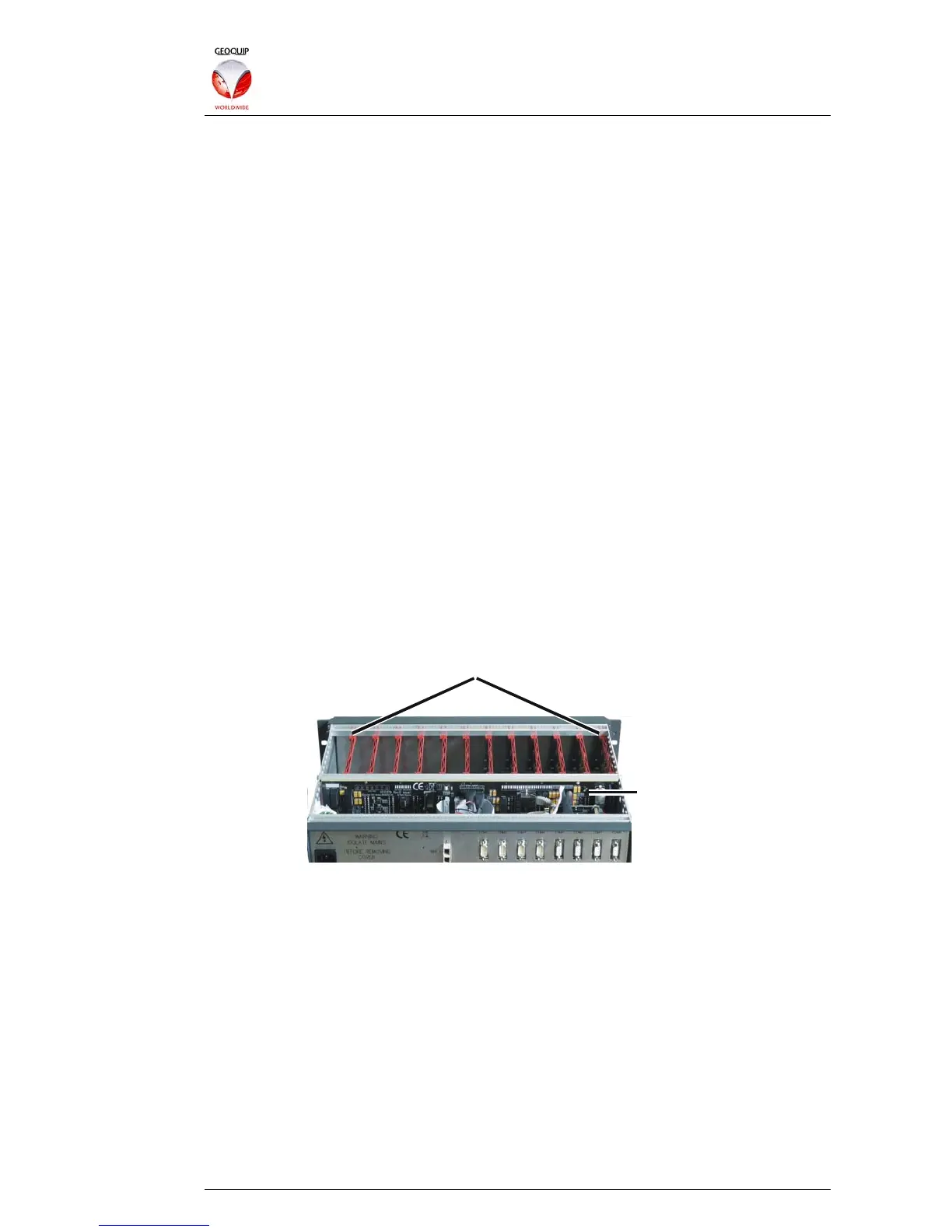
If you remove the Rack unit's top cover, you will see up to twelve plug-in cards at the
front of the Rack: these provide the analyser circuitry for the Interceptor cables, with
each card managing two Interceptors. The main Rack system board acts as the
backplane for these cards.
12 x Interceptor Processing Cards
System Board
The cards also have LEDs on the front edge, so if you remove the Comander front
panel you will see status LEDs for each Comander circuit – see section 3.1.1 below.
A third optional component of the Comander is the 1D Relay Rack – one or more
rackmount cases containing up to 512 isolated relays, which can be controlled by the
Comander Rack via a single serial connection. Each relay can be controlled
individually, either directly by the Comander in response to specific input conditions, or
by the Security Management System (usually referred to as the "SMS").
As well as the connections to its local Marshalling Box and optional 1D Relay Rack, the
Comander Rack has a number of other connections for serial and network devices on
its rear panel. These are detailed in the following sections.
1.2 Comander Networking
The core of a multi-unit Comander system comprises an Ethernet network, which is
used to connect the Comander units together, and also to connect alarm and
monitoring devices and control computers. Each Comander operates as a managed