Comander Perimeter Security System
Engineering and Installation Manual
Page 14 of 72
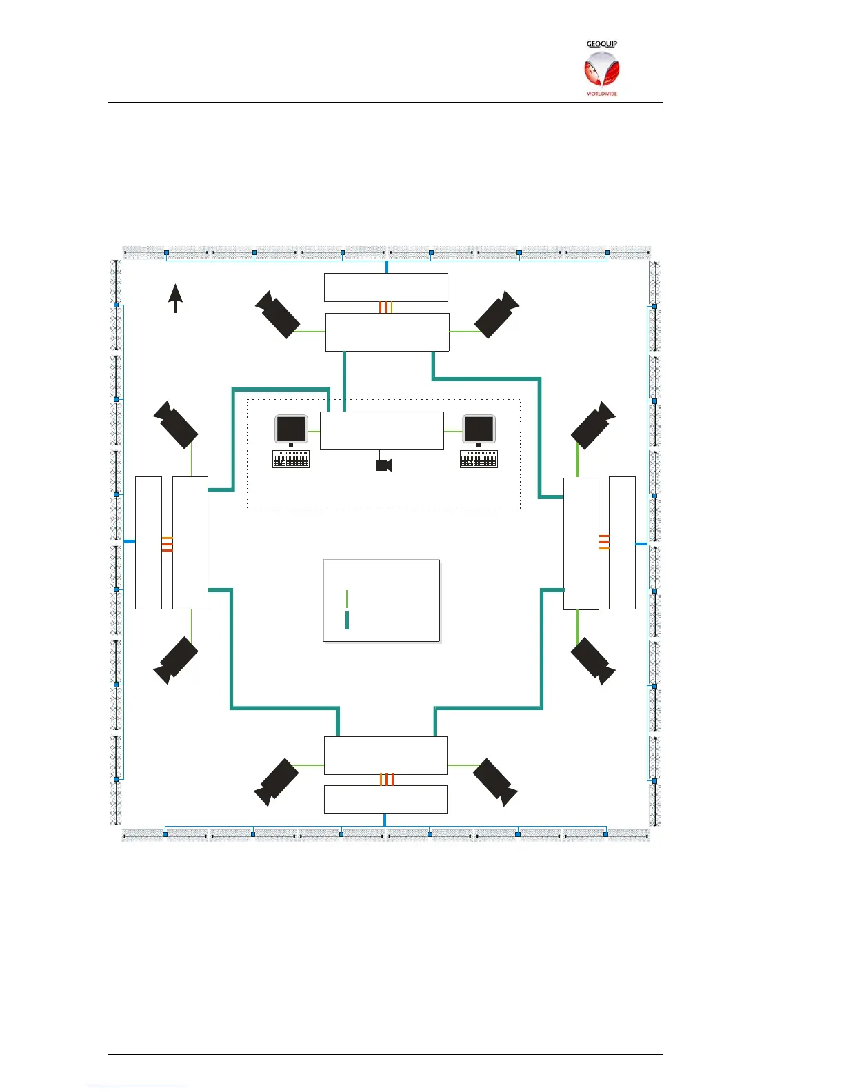
1.8.2 Longer Perimeters – a Comander Ring
A more typical Comander system installation uses a number of Comander units,
located around a perimeter, and connected together in a Ring Topology. There is also
a Comander Rack located in a Control Room, with a Geolog Vision SMS computer
attached to it. (Access gates have been deliberately omitted from this example to
simplify it.)
Marshalling Box
Marshalling Box
Marshalling Box
Marshalling Box
Rack
IP 10.2.3.104
Rack
IP 10.2.3.101
Rack
IP 10.2.3.102
Rack
IP 10.2.3.103
C
C
T
V
C
C
T
V
C
C
T
V
C
C
T
V
C
C
T
V
C
C
T
V
C
C
T
V
C
C
T
V
Rack
IP 10.2.3.100
Control Room
Geolog Vision
10.2.3.200
Audio
Camera Matrix
10.2.100.200
N
CAT5e Ethernet
Fibre Ethernet
KEY
1.8.2.1 Network Addressing
In this scenario the five Comander Racks monitor 48 Interceptor zones, with 24
associated Junction Box Tamper contacts in the junction boxes. The Racks are
assigned IP addresses within the subnet 10.2.3.0/24, and the Ring is connected using
the Rack's fibre Ethernet connectors.
As well as the Comander subnet, the Ethernet network here is also used to transport
CCTV data from eight IP cameras sited around perimeter, each of which is connected
to a CAT5e port on the nearest Comander Rack (maximum distance 100m). The
CCTV is monitored in the Control Room using a Camera Matrix. Note that the IP
addressing for the camera system uses subnet 10.2.100.0/24, a separate subnet from