Comander Perimeter Security System
Engineering and Installation Manual
Page 35 of 72
2.5.7.4 Collator Configuration Examples
In the example scenario illustrated in section 1.8.2 above, the SMS Collator is enabled
on the Comander Rack which is located in the Control Room. Alarm information is
collated by that Rack from the other Racks in the system, and annunciated to the SMS.
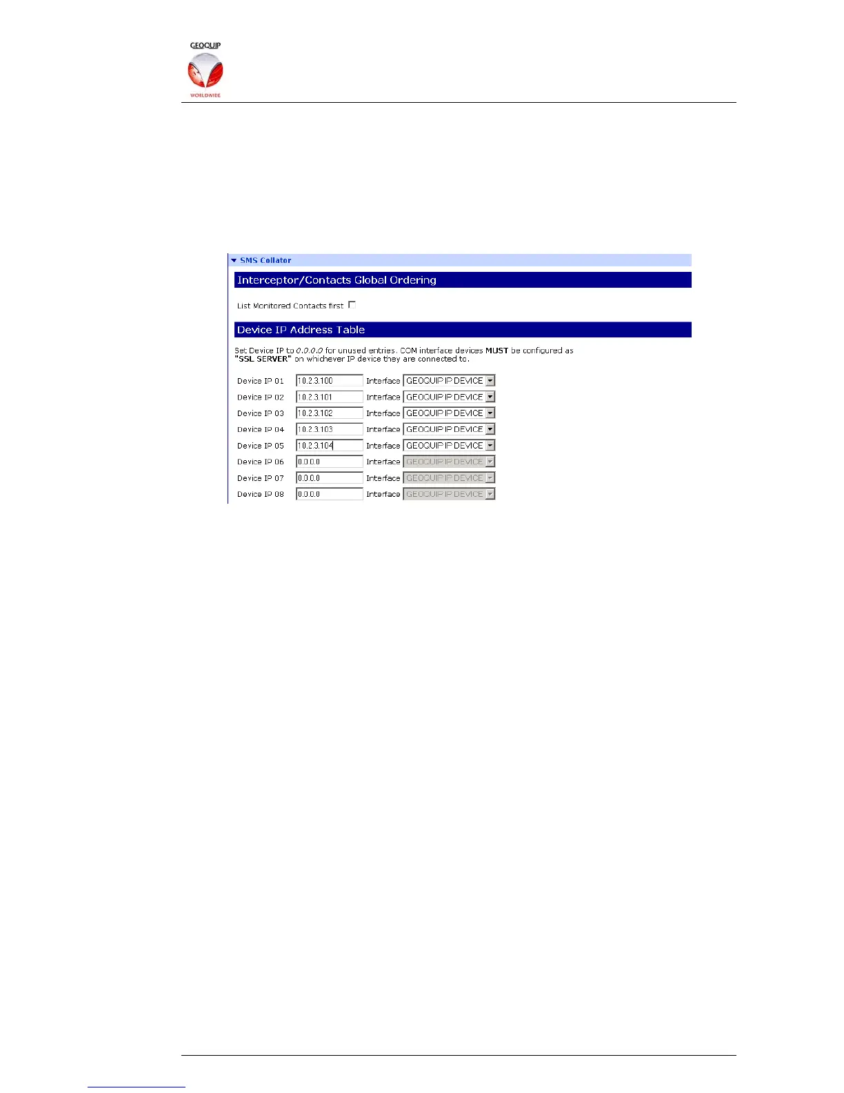
To configure the Control Room Rack as the Collator for this system, simply enter the IP
addresses of all the Comander units into the Collator page of the Configurator, with the
Interface option set to Geoquip IP Device:
This configuration will collate the circuits from the units listed in the order in which they
appear in the list.
The total number of circuits collated and presented to the SMS will depend on what
options are enabled in the different Rack units. For example, assume the following...
• Rack 10.2.3.100 (Control Room) does not have any Interceptor or Monitored
Contact connections;
• Each of the other Racks has 12 Interceptor and 6 associated Junction Box
Tamper circuits;
• Each of the other Racks has an additional 12 Monitored Contact inputs – these
might be gate or door switches (for example on the buildings or cabinets in
which the Racks are housed), or outputs from other detection systems.
• The Collator Rack does not have the List Monitored Contacts First option
enabled;
• Rack number 10.2.3.100 has Fixed/Diagnostic Circuits Enabled;
• The other Racks do not have Fixed/Diagnostic Circuits Enabled;
• Rack number 10.2.3.100 has RSTP enabled and the IPs of the other Comander
Racks entered in its Network Topology Configurator, as illustrated in section
1.8.2.3 above.