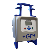
Introduction Operating manual MSA 4
3
1.2.2 Display
The display, a graphical LCD, is the main user interface of the welding machine. It shows
the steps to be executed in sequence, the fusion data, possible errors and alarm messages.
It is possible to change its brightness using the and buttons and then save permanently
the new value pressing the button, in case of visibility issues due to weather conditions.
The operation can be done only when the display shows the fitting icon.
1.2.3 Electrical switch
The MSA 4.0 (MSA 4.1) electro-fusion machine is equipped with an electrical switch powers
on/off, it is the ultimate command to be activated in case of emergency or internal fault of
the welding machine itself.
1.2.4 Ambient temperature sensor
The outside sensor measures the ambient temperature, to check the temperature is in the
permitted range (between -20° C and 50° C) and adjust the fusion time according to the
external conditions.
1.2.5 USB interface
The USB type-A interface available on the rear of the machine is the main interface for
communication purposes. Via USB the user can: retrieve the protocols data stored in the
machine, upgrade the software version of the machine. The connector is protected
against dust and water by a cap, which ensures an IP65 protection factor when properly
screwed.
1.2.6 Power Cable
The power cable is delivered with a Schuko plug for being connected to power supply at
230V 50 / 60 Hz.
The power source can be either the mains or a generator. In the latter case there are no
deterministic rules to select the right generator output power. Requirements will vary
depending on the efficiency of the generator as well as other factors, like the diameter of
the fittings going to be weld.
1.2.7 Welding Cable
The low voltage cable shall be connected to the fitting pins. As standard the terminals are
supplied with female connectors, Ø4mm.