Sensor Setup
Set Up Sensor with ATOS V7 Software
Page 25 (40)
atos_cs_rev01_en_rev-c 2012-09-03
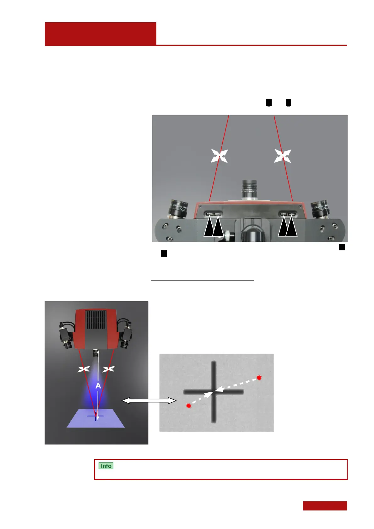
8.4.2 Adjust the Laser Pointers
In addition to the target, the ATOS COMPACT SCAN sensors have
two laser pointers (right and left) to determine the center of the meas-
uring volume. The laser pointers always have to be readjusted if the
measuring distance (see Sensor Configurations 4.1) changed. For
each laser pointer, two adjusting screws ( p and q ) are available at
the bottom side of the sensor.
The figure shows the adjustment possibilities for the laser pointers. The adjustment screws p
and q move the laser beam with respect to each other.
Steps to adjust the laser pointers
• You already set up the sensor according to section 8.4.
• Position the sensor at the measuring distance (see section 4.1 and
4.2) in front of a light surface.
• Remove the camera covers.
• Switch on the sensor (switch at the power supply unit).
• Switch on the laser pointers via the ATOS software.
• Adjust the laser pointers to the center of the projected cross.
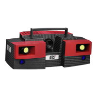
Adjust the laser pointers to the projected cross at measuring distance A
You cannot see the laser pointers in the 2D camera image if you use
an ATOS COMPACT SCAN sensor with blue light technology!