18
User Manual V1.5-2021-01-21 02 Installation Instructions
On-Grid
Back-up
LN PE
Meter
L
N
L
N
PE
L
N
PE
L
N
PE
RCD
E-BAR
E-BAR
RS485
RCD
CT
BMS
On-Grid
Back-up
LN PE
Meter
L
N
L
N
PE
L
N
PE
L
N
PE
E-N
Link
N-BAR
E-BARE-BAR
RCD
CT
RS485
BMS
RCD
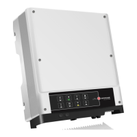
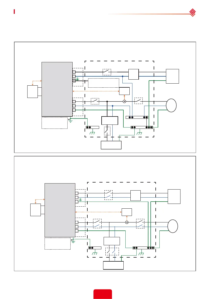
System connection diagrams
Note: According to Australian safety requirements, the neutral cables of the on-grid side and backup
side must be connected together. Otherwise, the backup function will not work.
Don't connect this
terminal for Australian and
New Zealand grid system !
Grounding screw
hole in the lower
right corner.
Grounding screw
hole in the lower
right corner.
Normal Loads
Battery
Battery
S-BP Series
Inverter
S-BP Series
Inverter
Distribution box
Distribution box
Smart
Meter
Smart
Meter
This diagram is an example for Australia, South Africa and New Zealand grid system.
This diagram is an example for grid system without special requirement on electrical
wiring connection.
Backup
Loads
Backup
Loads
Grid
Grid
Note: The Back-Up PE line and rack earth must be grounded properly and eectively.
Otherwise the Back-Up function may be abnormal when the grid fails.
Normal Loads
Note: After the inverter is installed and in order to avoid problems connected , please turn o the grid
power to check whether the Back-Up function is normal, in order to avoid problems in subsequent uses.
 Loading...