GMC-I Messtechnik GmbH 49
1)
U > 253 V, with 2 or 3-pole adapter only
2)
I
N
= 500 mA, max. U
N
= 250 V
3)
The measuring range respectively the transformation factor selected at the clamp
(I
L
=In: 1 mA...15 A/Out:1 mV/mA or Iamp = 1...150 A/1 mV/A) must be set in the
“TYPE” menu with the selector switch in the SENSOR position.
4)
The measuring range respectively the transformation factor selected at the clamp
(x 1, x 10, x 100, x 1000 mV/A) must be set in the “TYPE” menu with the selector
switch in the SENSOR position.
5)
at R
Eselektiv
/R
Egesamt
< 100
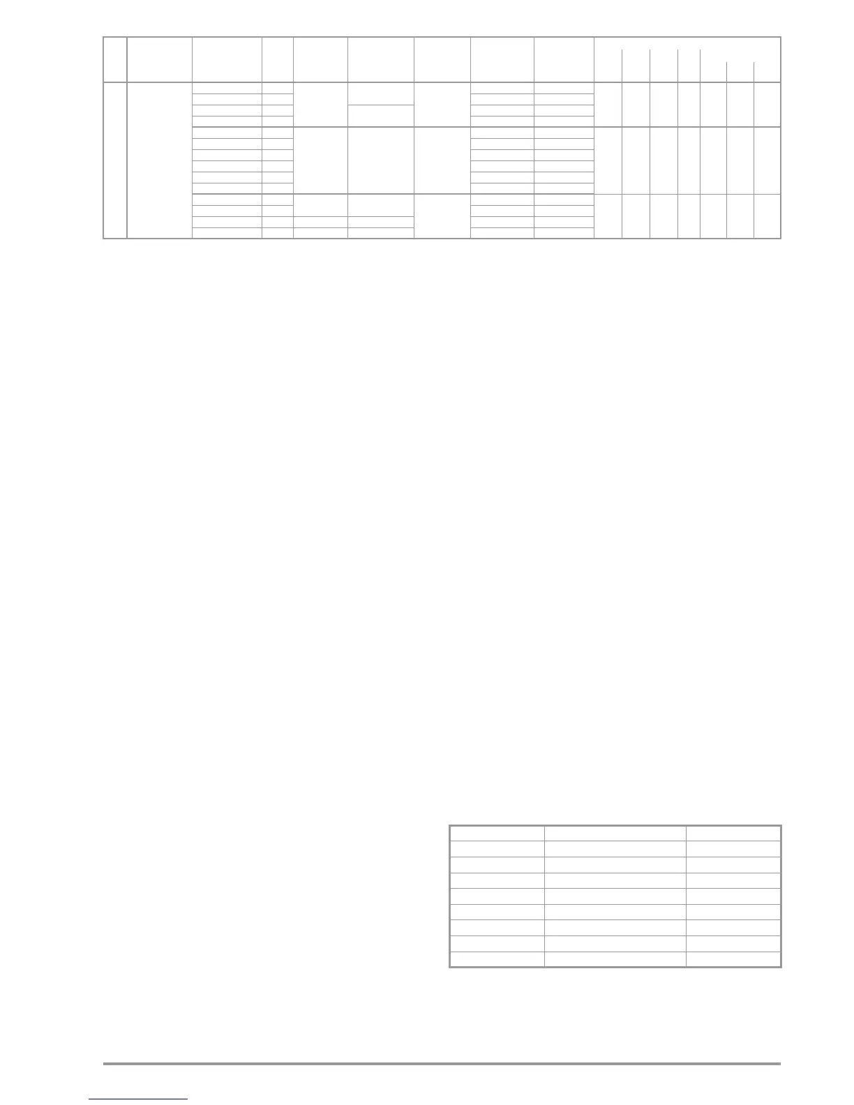
Reference Conditions
Line voltage 230 V 0.1%
Line frequency 50 Hz 0.1%
Meas. quantity frequency 45 Hz ... 65 Hz
Meas. quantity waveform Sine (deviation between RMS and
rectified value 0.1%)
Line impedance angle cos =1
Probe resistance
10
Supply voltage 12 V 0.5 V
Ambient temperature +23 C 2 K
Relative humidity 40% ... 60%
Finger contact For testing potential diff. at earth
Standing surface insulation Resistive only
Nominal Ranges of Use
Voltage U
N
120 V (108 ... 132 V)
230 V (196 ... 253 V)
400 V (340 ... 440 V)
Frequency f
N
16
2
/
3
Hz (15.4 ... 18 Hz)
50 Hz (49.5 ... 50.5 Hz)
60 Hz (59.4 ... 60.6 Hz)
200 Hz (190 ... 210 Hz)
400 Hz (380 ... 420 Hz)
Overall voltage range U
Y
65 ... 550 V
Overall frequency range 15.4 ... 420 Hz
Waveform Sine
Temperature range 0 C
... +40 C
Supply voltage 8 ... 12 V
Line impedance angle Corresponds to cos = 1 ... 0.95
Probe resistance < 50 k
Power Supply
Rechargeable batteries 8 x AA 1,5 V, we recommend
rechargeable batteries type
eneloop AA HR6, 2000 mAh
(Article no. Z502H)
Charger (Z502P) for 4 ... 10 cell battery packs
Input: 100 ... 240 V AC
Output: 16.5 V DC
3.5 mm diameter jack plug
(only suited for mains operation)
Charging time Approx. 4 hours
Number of Measurements with PROFITEST MTECH
(standard setup with illumination)
– for R
INS
1 measurement – 25 s pause:
approx. 1100 measurements
– for R
LO
Automatic polarity reversal/1
(1 measuring cycle) – 25 s pause:
approx. 1000 measurements
Overload Capacity
R
INS
1200 V continuous
U
L-PE
, U
L-N
600 V continuous
RCD, R
E
, R
F
440 V continuous
Z
L-PE
, Z
L-N
550 V (limits the number of
measurements and pause duration.
If overload occurs, the instrument is
switched off by means of a
thermostatic switch)
R
LO
Electronic protection prevents
switching on if interference voltage
is present
Protection with
fine-wire fuses FF 3.15 A 10 s,
fuses blow at > 5 A
Electrical Safety
Protection class II per IEC 61010-1/EN 61010-1/
VDE 0411-1
Nominal voltage 230/400 V (300/500 V)
Test voltage 3.7 kV 50 Hz
Measuring category CAT III 600 V or CAT IV 300 V
Pollution degree 2
Fusing, Terminals L and N 1 cartridge fuse-link ea.
FF 3.15/500G 6.3 mm x 32 mm
Electromagnetic Compatibility (EMC)
Product standard EN 61326-1:2006
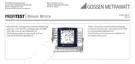
SEN-
SOR
I
L/Amp
0 ... 99.9 mA 0.1 mA
5 ... 1000 mA
3)
(10% rdg.+8d) (4% rdg.+7d)
l
100 ... 999 mA 1 mA (10% rdg.+3d) (4% rdg.+2d)
0 ... 99.9 A 0.1 A
5 ... 150 A
3)
(8% rdg.+2d) (3% rdg.+2d)
100 ... 150 A 1 A (8% rdg.+1d) (3% rdg.+1d)
0 ... 99.9 mA 0.1 mA
5 ... 1000 mA
4)
0.05 ... 10 A
4)
0.5 ... 100 A
4)
5 ... 1000 A
4)
(7% rdg.+8d) (4% rdg.+7d)
l
100 ... 999 mA 1 mA (5% rdg.+3d) (2% rdg.+2d)
1.0 ... 9.99 A 0.01 A (4% rdg.+2d) (2% rdg.+2d)
10.0 ... 99.9 A 0.1 A (4% rdg.+2d) (2% rdg.+2d)
100 ... 999 A 1 A (4% rdg.+1d) (2% rdg.+1d)
1.00 ... 1.02 kA 0.01 kA (4% rdg.+1d) (2% rdg.+1d)
0 ... 99.9 mA 0.1 mA
1 V/A 30 ... 1000 mA
4)
U
N
= 120/230/
400 V
f
N
= 50/60 Hz
(7%
rdg.
+100d)
(4%
rdg.
+100d)
l
100 ... 999 mA 1 mA (6% rdg.+12d) (3% rdg.+12d)
1.0 ... 9.99 A 0.01 A 100 mV/A 0,3 ... 10 A
4)
(6% rdg.+12d) (3% rdg.+12d)
10.0 ... 99.9 A 0.1 A 10 mV/A 3 ... 100 A
4)
(5% rdg.+11d) (2% rdg.+11d)
Func-
tion
Measured
Quantity
Display Range
Reso-
lution
Input
Impedance/
Test Current
Measuring Range Nominal Values
Measuring
Uncertainty
Intrinsic
Uncertainty
Connections
Plug
Insert
1)
2-Pole
Adapter
3-Pole
Adapter
Probe
Clamps
WZ12C Z3512A
MFLEX
P300
Interference Emission Class
EN 55022 A
Interference Immunity Test value Features
EN 61000-4-2 Contact / atmos. – 4 kV / 8 kV
EN 61000-4-3 10 V/m
EN 61000-4-4 Mains connection – 2 kV
EN 61000-4-5 Mains connection – 1 kV
EN 61000-4-6 Mains connection – 3 V
EN 61000-4-11 0.5 period / 100%

 Loading...