Control Board Replacement
3A3394E Repair - Parts 31
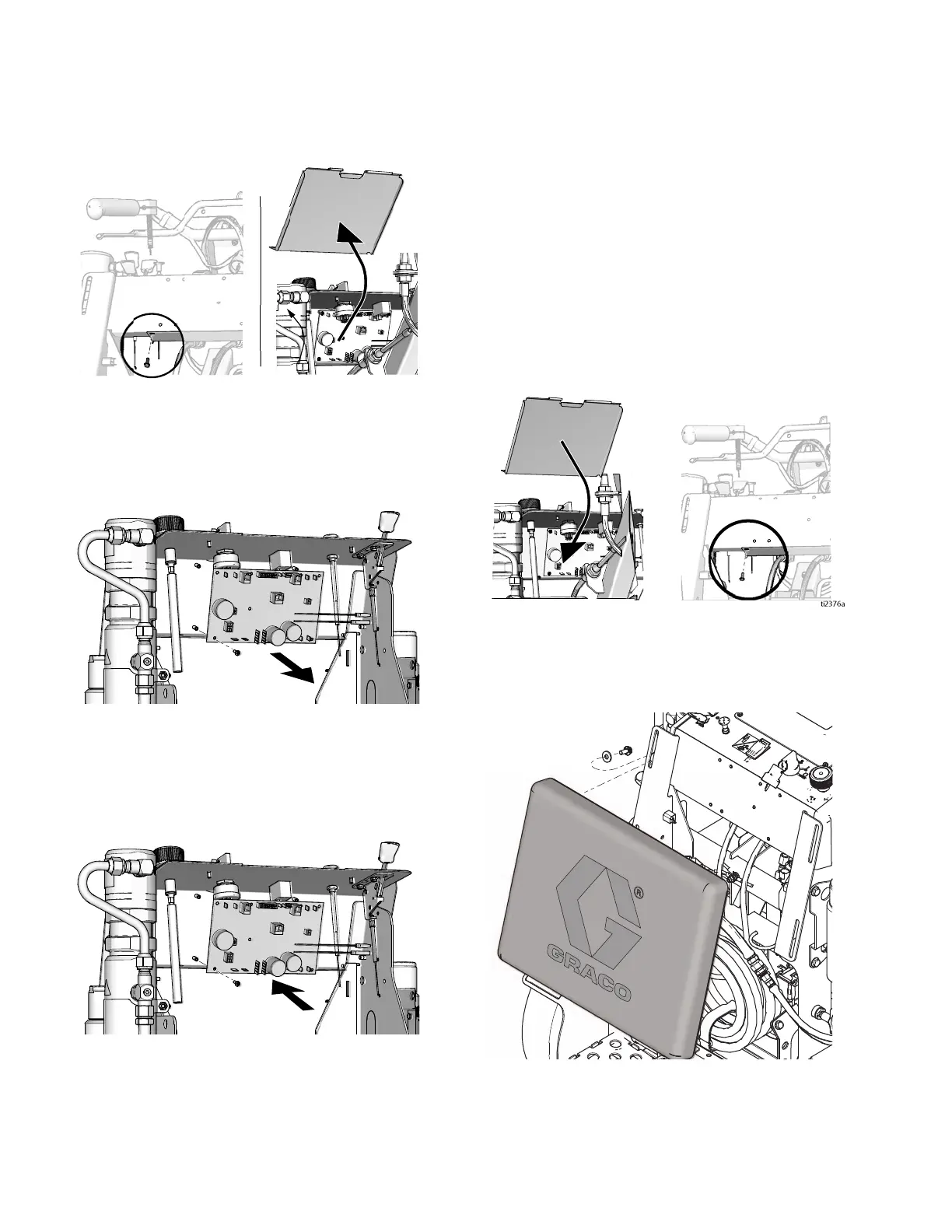
7. Remove two screws and splash shield.
8. Disconnect all wires from control board.
9. Remove eight control board mounting screws and
then remove control board.
Installation
1. Install control board with eight mounting screws.
2. Before connecting wires to control board, make sure
that all wires are routed above the two steering
cables.
3. Connect all wires to control board. See, Wiring Dia-
gram, page 68. Pump number 1 is on the left when
you stand in the operator position.
4. Bundle and secure wires with a cable tie just
inboard of the choke cable.
5. Bundle and secure wires with a cable tie just out-
board of the key switch.
6. Install fuse, see Fuse Replacement, page 34.
Check control, switches and display.
7. Install splash shield with two screws.
8. Install control shroud with six screws. See Removal
step 6.
9. Install pad and tighten four screws.
ti2376a
 Loading...