Spray Tip Charts
52 3A8099A
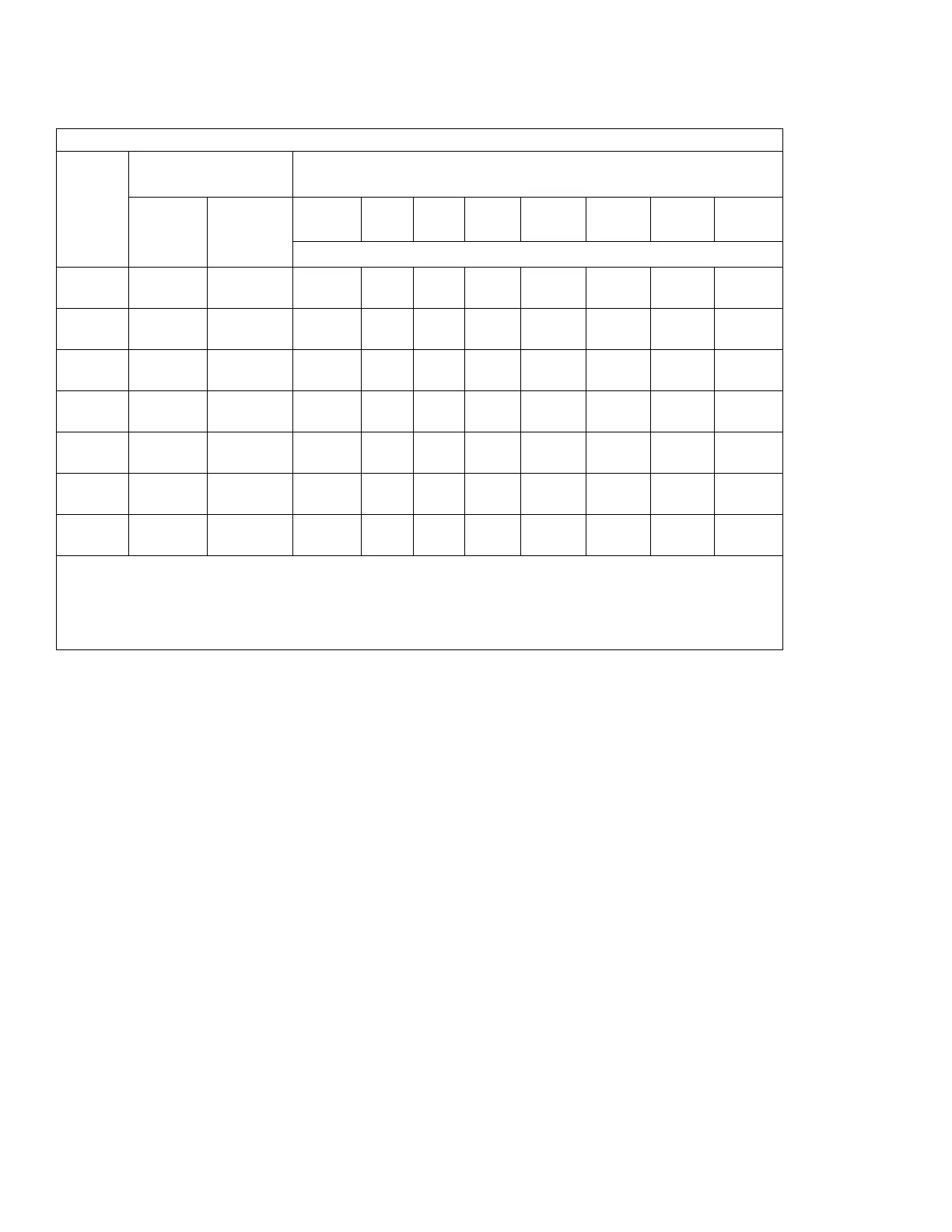
Table 2: AXF Fine Finish Pre-Orifice Spray Tips Matrix Table
Orifice
Size
in. (mm)
*Fluid Output
Maximum Pattern Width at 12 in. (305 mm)
in. (mm)
at 600 psi
(4.1 MPa,
41 bar)
at 1000 psi
(7.0 MPa,
70 bar)
2 to 4
(75)
4 to 6
(150)
6 to 8
(200)
8 to 10
(250)
10 to 12
(300)
12 to 14
(350)
14 to 16
(400)
16 to 18
(450)
Spray Tip Part No.
0.007
(0.178)
4.0 (0.1) 5.2 (0.15)
~306
0.009
(0.229)
7.0 (0.21) 8.5 (0.25) ~108 208 308 408 ~508 ~608
0.011
(0.279)
9.5 (0.28) 12.5 (0.37) 210 310 410 510 610 710
0.013
(0.330)
12.0
(0.35)
16.0 (0.47) 212 312 412 512 612 712
0.015
(0.381)
16.0
(0.47)
21.0 (0.62) --- --- ~314 414 514 614 714 ~814
0.017
(0.432)
--- --- ~316 416 516 616 716
0.019
(0.483)
--- --- --- --- ~518 ---
*Tips are tested in water.
Measured with NO airflow. Air assist will tend to reduce pattern lengths by 1 in. to 2 in.
~AXF tips only (testing - may delete later)
Fluid output (Q) at other pressures (P) can be calculated by this formula: Q = (0.041) (QT) where
QT = fluid output (fl oz/min) from the above table for the selected orifice size.