Component Identification - Project Painter Plus
12 3A0248C
Component Identification - Project Painter Plus
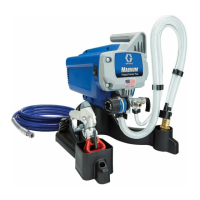
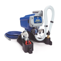
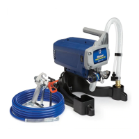
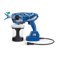
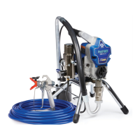
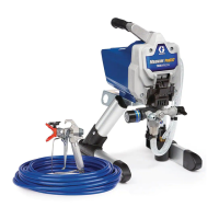
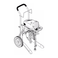
A Airless spray gun Dispenses fluid.
B Power switch Turns sprayer ON and OFF.
C Pressure control knob
Increases (clockwise) and decreases (counter-clockwise) fluid pressure in
pump, hose, and spray gun.
C1 Setting Indicator
To select function, align symbol on pressure control knob with setting
indicator, page 14.
D Pump fluid outlet fitting Threaded connection for paint hose.
G Suction tube Draws fluid from paint pail into pump.
H Prime tube (with diffuser) Drains fluid in system during priming and pressure relief.
J Prime/Spray valve
• In PRIME position directs fluid to prime tube.
• In SPRAY position directs pressurized fluid to paint hose.
• Automatically relieves system pressure in overpressure situations.
L Inlet screen Prevents debris from entering pump.
M Paint hose Transports high-pressure fluid from pump to spray gun.
N Handle Used to help transport sprayer.
Q Tip guard Reduces risk of fluid injection injury.
R Reversible spray tip
• Atomizes fluid being sprayed, forms spray pattern and controls fluid flow
according to hole size.
• Reverse unclogs plugged tips without disassembly.
S
Gun trigger safety lever
(page 14)
Prevents accidental triggering of spray gun.
T Gun fluid inlet fitting Threaded connection for paint hose.
U Power Flush attachment
Connects garden hose to suction tube for power flushing water-base
fluids.
V Gun fluid filter Filters fluid entering spray gun to reduce tip clogs.
W Pail Hook Holds material pail.
X Power Cord Supplies Project Painter Plus with electricity.