Section 4: System HydraulicsPage 12
7
12
13
6
11
10
15
16
17
18
19
21
20
The siting of room thermostats is
critical to ensure satisfactory
performance of the heating system.
Refer to the Aerona³ heat pump
installation instructions for more
information.
Grant Sealed System Kit
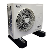
Aerona ASHP
Flexible hose¹
Isolation valve¹
Grant External Volumiser***
Anti-Vibration Mounts²
Flow sensor¹
Grant Mag One magnetic filter kit²
Wiring Centre Smart Controls¹
Touch Screen Display¹
Room thermostat
Automatic air vent
Cylinder immersion heater
DHW cylinder
Immersion heater relay²
Drain point²
Removable filling loop²
Double check valve²
Pressure gauge²
Expansion vessel²
Tundish²
Pressure relief valve²
Automatic system bypass²
Circulating pump
UFH manifold
3-Port diverted valve²
Thermostatic radiator valve
3-Port mixing valve²
Water sensor¹
*Outputs available: 6, 10, 13 & 17 kW
¹Supplied with the HPIDR32SMART* Smart Controller Kit
²Supplied with HPIDR32PACKQ
1
2
3
4
5
6
7
8
9
10
11
12
13
14
15
16
17
18
19
20
21
22
23
24
25
26
27
28
Item Description
8
3
2
3
1
4
***
**
5
14
F
R
3
2
3
1
2
4
5
IMPORTANT
The below diagram shows the Flow (outlet) and
Return (inlet) connection positions for HPID6R32
models ONLY.
22
Automatic bypass
required unless there is
an open radiator on the
radiator circuit (such as
a towel rail).
**Compression elbow c/w air vent
(supplied with HPIDVOL30EXT6)
9
24
23
25
Port A
Port B
26
28
27
28
! NOTE !
This system schematic should be read in conjunction with the Grant
Aerona Smart Control installation instructions and wiring diagram
HPCS-Q001E.
! NOTE !
Please refer to the Aerona ASHP installation instructions for details
of the flow and return connections at the heat pump.
IMPORTANT
For positions of the Flow (outlet) and Return (inlet)
connections on HPID10R32, HPID13R32 and
HPID17R32 models, see above.
! NOTE !
+The 3 port mixing valve mounted on the right hand side of the heating
system will have the valve body scale plate indicating 0-10 in clock-
wise direction as well as the black scale plate for the actuator. Refer
to the Smart Controller Installation instructions manual for more detail.
B
I II
+
! NOTE !
***30L external volumiser or low loss header are available as an
optional component where there is insufficient system volume or
where hydraulic separation is required (HPIDVOLEXT30/HPIDSYSLLHKIT).
4.5 HYDRAULIC CONNECTIONS - PACK Q
Grant UK Drawing Number: HPCS-Q001S

 Loading...