Appendix B: Wireless Thermostat and ReveiverPage 44
B.1 GENERAL
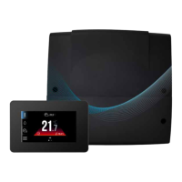
The Grant Wireless receiver & thermostat are designed to provide
wireless circuit control via the Grant Aerona Smart controller.
The thermostat should be installed in a suitable location to
monitor the circuit, e.g., First oor hallway, and is designed to
maintain a target temperature. by sending a radio signal to the
module connected to the wireless receiver.
The thermostat on the backlit LCD display shows information
about thecircuit temperature value, selected operating mode,
current time with simultaneous clock synchronization with the
touchscreen display.
B.2 INSTALLING WIRELESS RECEIVER
The wireless receiver should be mounted on a wall near the
installation location of the wiring centre. If the radio connection is
poor, try placing the wireless receiver in other places. Moving the
wireless receiver even by a few centimetres can aect the quality
of the connection.
! NOTE !
Placing a wireless receiver in a metal casing, e.g. a
mounting box, a metal boiler casing, etc. will block the
radio signal and thus interfere with the operation.
The radio module should be screwed to the wall with mounting
screws. Access to holes for screws is obtained after unscrewing
the cover of this module. Refer to Figure B.1.
Screw Hole
Screw
Figure B-1: Wireless receiver wall xings
Terminals D +, D-, GND, 12VDC of the Wireless receiver should
be connected to the G1 socket of the wiring centre.
Appendix B
Wireless Thermostat and Receiver
D- D+
LED
P
GND
+12V
Figure B-2: Wireless receiver wiring
! NOTE !
Ensure the correct polarity of the connection of the D+,
D- signals and the GND, +12V power supply between the
thermostat and the wiring centre. Incorrect connection
may lead to damage to the main controller or errors in its
operation.
The maximum cable length depends on the cross-section of the
wires. For a 0.5 mm² wire, it should not exceed 30m. The cross-
Section should not, however be less than 0.5 mm².
B.3 WIRELESS THERMOSTAT
The wireless thermostat is intended for installation only in a dry
habitable location and should placed on a at surface (as a free-
standing device) in a room representative for a given heating
circuit. After choosing the place of installation, make sure that:
• The selected location is free of excessive humidity and the
ambient temperature of the thermostat should be within the
range of 5..35°C.
• The chosen location should ensure free air circulation and
should be located away from heat-emitting sources, e.g.,
electronic equipment, replace, heater and direct sunlight.
• The selected place must not cause interference or a lack of
radio signal.
4 x 0.5mm
2
wire
max length 30m

 Loading...