Section 5: Electrical Connections Page 15
23 24 25 26 27 28 29 30 31 32 33 34 35 36
H2-S H3-S HDW BT BB WS
LOCK
GND
GND
IN
GND
FLOW
LE
ISM
+12V
GND
D+
D-
RT1
37 38 39 40 41 42 43 44 45 46 47 48 49 50
13 14 15 16 17 18 19 20 21 22
3 4 5 6 7 8 9 10 11 12
1 2
L N
L N L
L N L N L N
N L
L N L
F1
15V
230V AC / 50Hz
G1
G2
G3
M-BUS
B
ecoNET
F4
IN
GND
GND
HEMS T2
RT2 RT3
D+
D-
+5V
D+
D-
GND
3
3
32
2
1
2
L
H2-M
H3-M
Z-P/Z3D
ON OFFON OFF
ON OFF
N PE
PE
H1-P
PE
H2-P
PE
H3-P
PE
C-P
H2
PE PE PE
230V~
H1
F3 F2
T1
G4
M MM
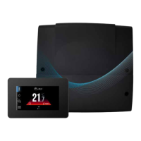
Figure 5-3: Wiring centre - Terminals
Table 5-2: Wiring Centre Terminals
Label Terminal Numbers Description
230V ~ 1 & 2 Mains Live and Neutral
H2-M 3, 4 & 5 Circuit 2 Mixing valve - 2 x 230V Lives (ON and OFF) and Neutral
H3-M 6, 7 & 8 Circuit 3 Mixing Valve - 2 x 230V Lives (ON and OFF) and Neutral
Z-P/Z3D 9 & 10 DHW Pump/3-Port Diverter Valve
C-P 11 & 12 Secondary Circulation Pump
Flow 31 & 32 Flow sensor I/O & Ground
LE 33 & 34 Electricity Meter
G1 Terminal Set Touchscreen & Thermostat connection terminals (RT1, RT2, RT3)
G2 M-BUS Modbus connection to the Aerona Heat pump.
G3 G3 Socket Connection port for ecoNET cable
G4 Terminal Set +12V, Ground, D+, D-
H1-P 13 & 14 Circuit 1 230V Switched Live and Neutral
H2-P 15 & 16 Circuit 2 230V Switched Live and Neutral
H3-P 17 & 18 Circuit 3 230V Switched Live and Neutral
H1 19 & 20 Switch for Immersion Relay (Buer)
H2 21 & 22 Switch for Immersion Relay (DHW Cylinder)
H2-S 39 & 40 Circuit 2 Water temperature sensor
H3-S 41 & 42 Circuit 3 Water temperature sensor
HDW 43 & 44 DHW Cylinder Water temperature sensor
BT 45 & 46 Buer Upper Water temperature sensor
BB 47 & 48 Buer Lower/Low Loss Header temperature sensor
WS 49 & 50 Outdoor Weather sensor
T1 37 & 38 External Volt-free switch for Circuit 2
T2 26 & 27 External Volt-free switch for Circuit 3
LOCK 23 & 24 Not used
HEMS 25 & 26 Not used
5.4 WIRING CENTRE LAYOUT

 Loading...