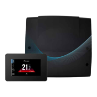
Appendix A: Wired Thermostat Page 43
Table A-1: Wired (& Wireless) theromstat LCD symbols
Symbol Symbol descirption
Alarm symbol
Schedule - Thermostat is schedule managed
Parameter editing
Heat demand
Radio signal (Wireless Thermostat only)
Low battery indicator (Wireless Thermostat only)
Decrease parameter
Conrm
Increase parameter
A.4 PAIRING
The wired thermostat should be connected as part of the Smart
Controller conguration creator for the circuit that the thermostat
will measure. To pair again you can follow this within the individual
circuit settings to re-pair to the Grant Aerona Smart controller.
• Access the circuit you wish to pair with a wired thermostat
panel from the Circuit settings within the System settings
menu (Refer to Section 8) and select the Thermostat
option from the menu and conrm you wish to overwrite if a
thermostat is already present on the circuit.
• The pairing wizard will begin and will instruct you to set put
the desired wired thermostat into pairing mode.
• Follow the on-screen prompts. Hold the up and down buttons
simultaneously for 2 seconds. The screen will change to
display you have entered the user menu where you then
select parameter 03 in the user menu of the thermostat. "PAr"
will be displayed on the screen. After accepting with button,
the pairing will start (the word "PAr" begins to ash).
• Conrmation of the pairing will be conrmed by the message
"END" and "Succ" on the thermostat.
• After pairing a room thermostat holding the tick down will
return you rst to the previous menu and then the back to the
main screen in 2 second intervals.
A.5 CHANGING SETPOINT TEMPERATURE
Tapping the up or down arrows will prompt the thermostat into
the check/editing of target temperature causing the current target
saved temperature to ash.
The rst tap of the arrow will trigger the edit temperature function
but will not change the value. Tapping the arrow again will then
change the value either up or down. Tapping the tick will conrm,
save and exit.
Not conrming a new target with 5 seconds of inactivity will cause
the thermostat to exit the editing mode without changing the target
temperature.
! NOTE !
Holding the up or down arrows for more than 2 seconds
will cause a fast change to the parameter.
A.6 HOTEL MODE
Hotel mode can disable the wired thermostats ability to change
the Smart Controller parameters and schedules. We recommend
this be activated to avoid conicting programmed settings
between the wired thermostat and the Grant Aerona Smart
controller.
1. To access the service menu press and hold the down arrow
and the conrmation tick capacitive buttons for 2 seconds.
After which you will need to enter the number sequence 1410
and conrm with the tick.
2. To enter the password you will need to cycle each of the
4 digits with the up or down arrow and conrm that digit
with the tick. On the conrmation of the fourth digit you will
continue to the service menu.
3. Navigate to parameter 2 and select Hotel mode with the tick.
Default setting for hotel mode is o and the arrows will cycle
through options. Ensure On is visible and conrm.
4. Holding the tick for 2 seconds will save and exit the menu
back to the main screen.
A.7 ERROR CODES
The Grant Aerona Smart controller communicates alerts to the
thermostat panels when present in the system. Refer to Table A-2
for determining the fault.
Table A-2: Theromstat alarm codes
Code Alert descirption
1 Outside temperature sensor error
2 1 - No communication with the controller
3 No compatibility of programs
4 3 - Panel temperature sensor error
5 DHW sensor error
6 Upper buer temperature sensor error
7 6 - Lower buer temperature sensor error
8 Circuit 2 temperature sensor error
9 Circuit 3 temperature sensor error
10 Anti-freeze active
12 No communication with the thermostat
13 No communication with thermostat circuit 1
14 No communication with thermostat circuit 2
15 No communication with thermostat circuit 3
16 15 - alarm from digital input
17 No ow detected
18 Too often no ow detected
20 19 - No communication with heat pump module
21 Circuit 4 temperature sensor error (not used)
22 Circuit 5 temperature sensor error (not used)
23 Circuit 6 temperature sensor error (not used)
24 Circuit 7 temperature sensor error (not used)
25 No communication with thermostat circuit 4 (not used)
26 No communication with thermostat circuit 5 (not used)
27 No communication with thermostat circuit 6 (not used)
28 No communication with thermostat circuit 7 (not used)
98 Service alarm
100-140 Alarms from heat pump

 Loading...