Section 3: Installation Information Page 13
3.9 Hydraulic Diagrams
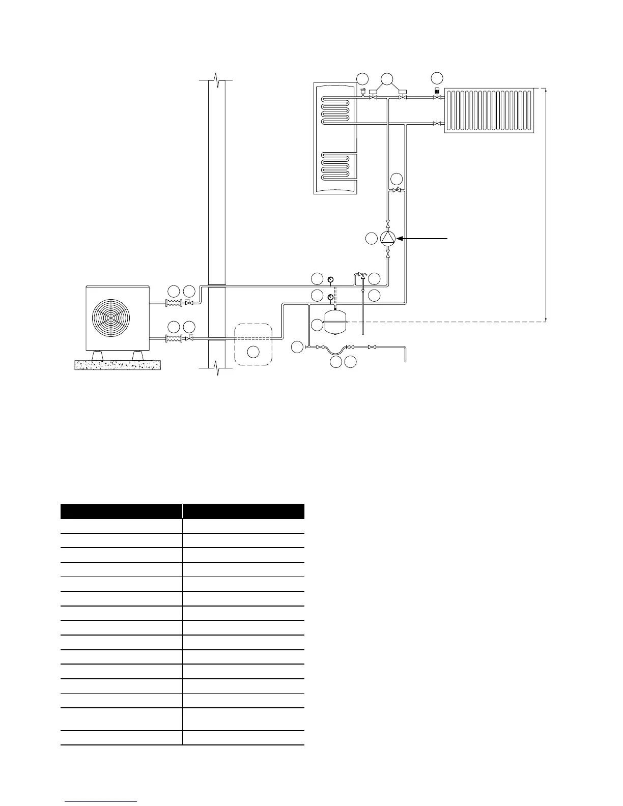
3.9.1 S-plan type with Buffer (optional)
2
1
2 3
4
5 6
7
8
9
15
Static head of system
10
11
10
11
13
14
12
Figure 3-4: Monovalent system - with optional buffer and S-Plan type controls
The above system diagram is only a concept drawing, not a detailed engineering drawing, and is not intended to describe
complete systems, nor any particular system.
It is the responsibility of the system designer, not Grant UK, to determine the necessary components for and configuration of the
particular system being designed including any additional equipment and safety devices to ensure compliance with building and
safety code requirements.
Table 3-5: Key
Key Description
1 Expansion vessel
2 Pressure gauge
3 Pressure relief valve
4 Tundish
5 Removable filling loop
6 Double check valve
7 Automatic air vent
8 Thermostatic radiator valve
9 Automatic bypass
10 Flexible hose
11 Isolation valve
12 Buffer (optional)
13 Motorised 2-port valves
14
Optional additional circulating pump
(refer to Section 8.3.7)
15 Drain point
Optional