Section 3: Installation Information Page 15
3.12 Installation Checklist
Location and positioning
• The vibration damping feet/shoes are fitted (if supplied)
• The heat pump is fixed to the surface or mountings that it rests
on
• Maintenance clearances comply with those given in this manual
• The position of the remote controller complies with the guidance
given in this manual
• All safety requirements have been complied with
Water circuit pipework and appliances
• Water connections have been carried out as per the information
in this manual
• All water connections are tight with no leaks
• The magnetic in-line filter is installed on the primary circuit return
as close to the heat pump as possible but still within the building
and in a position that is easy to access for maintenance
• The pressure gauge with a suitable scale is installed on the
sealed system pipework or expansion vessel manifold
• The connection pipes are suitably supported so that these do not
weigh on the appliance
• The expansion vessel installed on the heating circuit is suitably
sized
• The low-loss header or buffer tank is installed if the water content
is insufficient (16kW unit only - refer to Section 3.8)
• The water circuit has been thoroughly flushed
• The air vent valves are installed at the highest points on the
system
• There is no air in the system (vent if necessary)
• The shut off valves are installed on the inlet/outlet of system
circuit
• The drain valves are installed at the lowest points in the system
• The flexible hoses are installed on the inlet/outlet of system circuit
• The system water content complies with the specification in the
manual
• The DHW immersion heater has been installed in DHW tank for
Legionella prevention
• Suitable water flow rate for operation of the entire heat pump is
achieved as specified in this manual. Refer to Section 9.12
• All pipes are insulated with suitable vapour barrier material to
prevent formation of condensation and heat loss, with control
and shut-off devices protruding from the insulation
Electrical connections
• All electrical connections are secure
• Electrical connections have been carried out correctly
• Voltage is within a tolerance of 10% of the rated voltage for the
heat pump (230V)
• Electrical power supply complies with the data on the rating plate
and as specified in the manual
• The earth wires are connected securely
2. The second two digits will then blink. Use the ‘Up’ and ‘Down’
buttons to change these two digits to 99 and then press the ‘+’
(6) button.
3. The parameter value on the display will now be ‘0’.
4. Use the ‘Up’ and ‘Down’ (8) buttons to change the parameter
value to “738” and then press the ‘Set’ (7) button.
Now, reset the value for parameter 4300 to 0 (disabled):
1. The first two digits of the 4-digit parameter number (the
parameter group number) will blink.
2. Set the parameter group number to 43 using the ‘Up’ or ‘Down’
(8) button.
3. Press the ‘+’ (6) button and the second two digits (the
parameter code) will blink.
4. Set the parameter code number to 00 using the ‘Up’ or ‘Down’
(8) button.
5. Press ‘Set’ (7) button and the parameter value 4300 (1 =
enabled) will be displayed and will blink.
6. Reset the parameter value 4300 to 0 (disabled) using the ‘Up’ or
‘Down’ (8) button.
Repeat this process to reset the values of parameters 4310, 4320
and 4330 to 0.
Return to normal operation:
Press and hold the ‘Menu’ (3) and the ‘-‘ and ‘+’ (6) buttons together
for 3 seconds or simply leave the remote controller for 10 minutes.
Do NOT disable the heat pump antifreeze function unless a
suitable concentration of glycol is present in the system water.
Refer to Table 3-6. If there are any leaks of water from the
heating system and the system requires topping up then the
concentration of ethylene glycol must be checked and topped
up as required.
Failure to follow this instruction will invalidate the product
guarantee.
NOTE
!
3.11 Completion
Please ensure that the heat pump commissioning form (supplied
with the heat pump) is completed in full and that it is signed by the
householder/user.
Leave the copy with the user and retain one copy for your own
records.
Ensure that these installation and servicing instructions and the user
instructions are handed over to the householder.
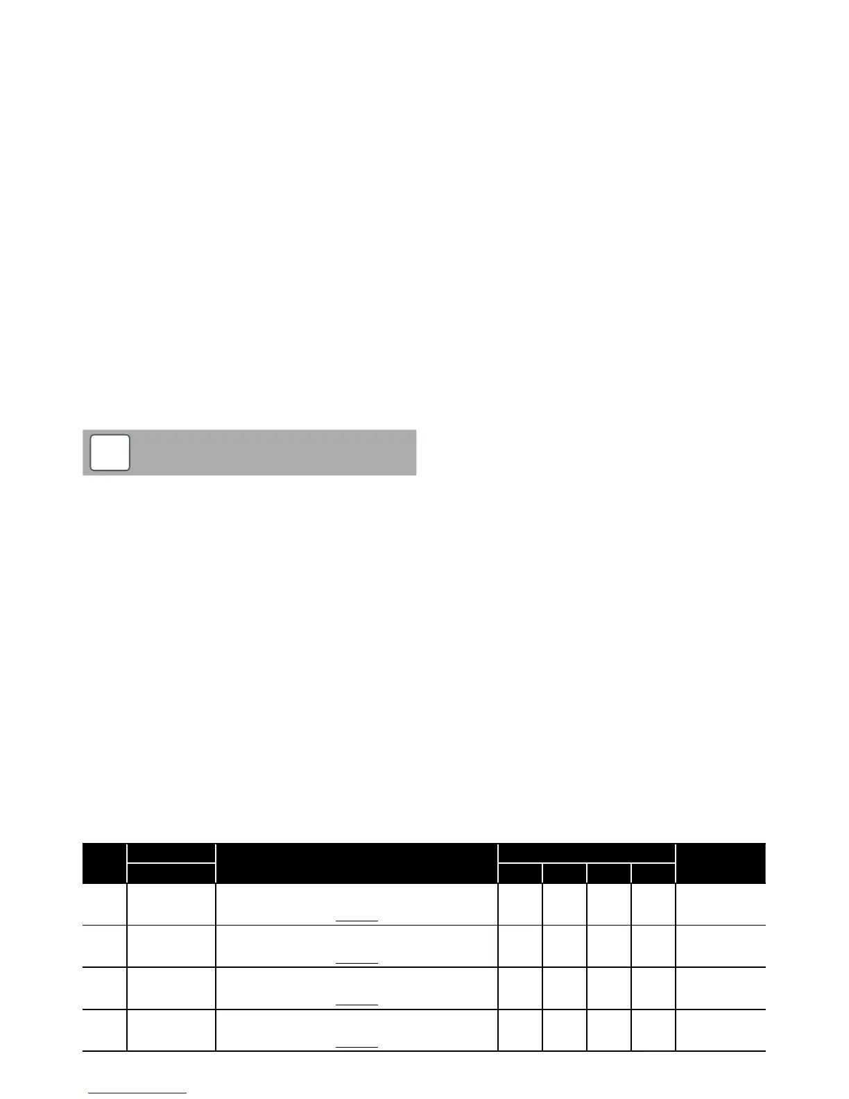
Table 3-8: Frost protection parameters
Level
Parameter
Function description
Display and input value
Remarks
Group Code Default Min. Max. Unit
S 43 00
Frost protection on room temperature
0=disable
1=enable
1 0 1 -
S 43 10
Frost protection by outside temperature
0=disable
1=enable
1 0 1 -
S 43 20
Frost protection based on outgoing water temperature
0=disable
1=enable
1 0 1 -
S 43 30
DHW storage frost protection
0=disable
1=enable
1 0 1 -