Section 3: Installation InformationPage 10
3.3 Regulations
Installation of a Grant Aerona³ heat pump must be in accordance with
the following recommendations:
• National Building Regulations, e.g. Approved Document G
• Local Bylaws (check with the Local Authority for the area)
• Water Supply (Water Fittings) Regulations 1999
• MCS Installer Standards (if applying for the Renewable Heat
Incentive)
• MIS 3005 (Requirements for contractors undertaking the
supply, design, installation, set to work commissioning and
handover of microgeneration heat pump systems)
• MCS 021 (MCS Heat Emitter Guide for Domestic Heat
Pumps)
The installation should also be in accordance with the latest edition of
the following standards and codes of Practice:
• BS 7671 and Amendments
• BS EN 12831
3.4 Heat Pump Location
3.4.1 Selection of position
• Consider a place where the noise and the air discharged will not
affect neighbours.
• Consider a position protected from the wind.
• Consider an area that reflects the minimum spaces
recommended.
• Consider a place that does not obstruct the access to doors or
paths.
• The surfaces of the floor must be solid enough to support the
weight of the heat pump and minimise the transmission of noise
and vibration.
• Take preventive measures so that children cannot reach the unit.
• Install the heat pump in a place where it will not be inclined more
than 5°.
• When installing the heat pump where it may exposed to strong
wind, brace it securely.
• If the Aerona³ heat pump is to be installed within 1 mile of the
coast, avoid siting facing the sea.
• If the Aerona³ heat pump is to be installed within 15 miles of the
coast, the evaporator must be sprayed with AFC50 and this must
be repeated on each annual service.
Decide the mounting position as follows:
1. Install the heat pump in a location which can withstand the
weight of the heat pump and vibration. Please make sure it is
installed level.
2. Provide the indicated space to ensure good airflow.
3. Do not install the heat pump near a source of heat, steam, or
flammable gas.
4. During heating operation, condensate water flows from the heat
pump. Therefore, install the heat pump in a place where the
condensate water flow will not be obstructed.
5. Do not install the heat pump where strong wind blows directly
onto the heat pump or where it is very dusty.
6. Do not install the heat pump where people pass frequently.
7. Install the heat pump in a place where it will be free from adverse
weather conditions as much as possible.
3.4.2 Noise Level
All heat pumps make a noise. Discuss the potential nuisance factor
with the end-user when considering the final position of the heat
pump. Take opening windows and doors into account. It is not
essential for the heat pump to be positioned next to a wall of the
house. Behind an out-building may be more suitable so discuss the
options with the end-user.
3.4.3 Orientation
The North face of the building will usually have colder ambient air
than any other side. To ensure maximum efficiency from the Grant
Aerona³ heat pump, position the heat pump on a warmer side. In
order of preference, site the heat pump on a South face followed by
either South East or South West, then by East or West. Only install on
a North face if there is no other alternative.
3.5 Preparation for Installation
3.5.1 Base
The heat pump should be installed on a flat trowelled finished
concrete base 150mm thick. This base should extend at least 150mm
beyond the heat pump on three sides.
To avoid bridging the DPC, leave a gap of at approximately 150mm
between the concrete base and the wall of the house.
The heat pump must be raised up from the base by approximately
100mm on suitable anti vibration mounts or blocks.
3.5.2 Clearances
The following minimum clearances must be used to enable the
product to be easily commissioned, serviced and maintained and
allow adequate air flow in and out of the heat pump.
Refer to Table 3-1 and Figure 3-2.
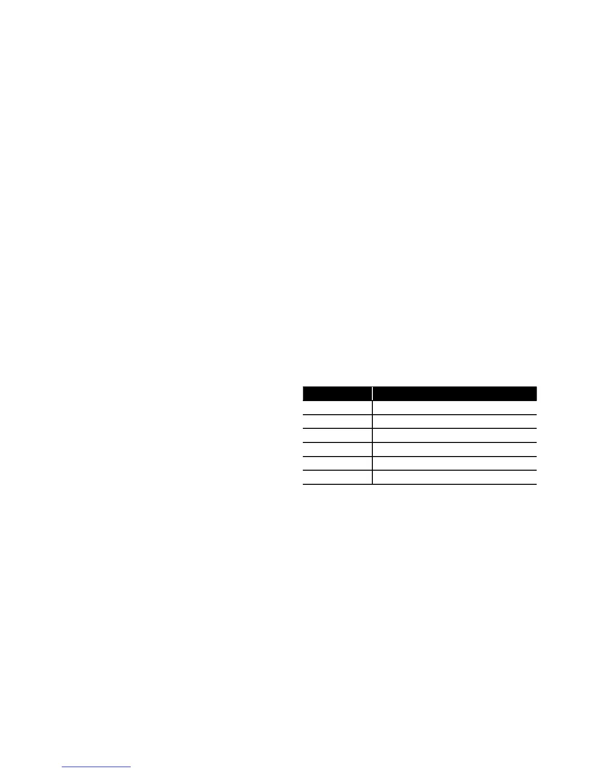
Table 3-1: Clearances
Aspect Minimum clearance required (mm)
To p 300
Bottom Approximately 100*
Front 600
Rear 300
Left 100
Right 600
* Height of A/V mounts (product code: HPIDFOOT/KIT)