Section 7: Remote Controller Page 31
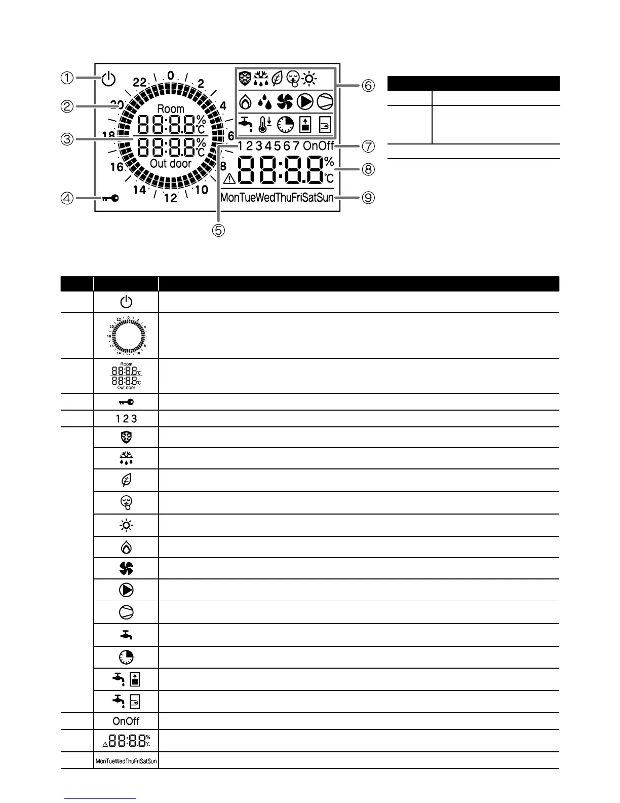
7.6 Display Panel
For guidance on the operation and setting of the remote controller, refer to Section 9 (Commissioning).
Table 7-11: Display panel
No. Icons Description
1
Power is ON, but ON/OFF switch is OFF (the heat pump is stopped)
2
Indicates current time of day.
3
Room air temperature, Outdoor temperature
4
Key lock is active
5
Display in time band setting
6
Frost protection is active
Defrost cycle is active
Low tariff mode is enabled
For low tariff mode, an external timer must be connected. Refer to Section 6.
Night mode is enabled
For night mode, an external timer must be connected. Refer to Section 6.
When this symbol is lit, heating mode is enabled. When this symbol is flashing, the heat pump is in heating mode, however the
heating is stopped for the production of DHW which has priority
Not available
Heat pump fan is active
System pump is active
Compressor active
Flashing: compressor delay
Indicates DHW demand
On: demand
Not available
Not available
Not available
7
Not available
8
Display alarm icon, and indicate error code
Clock, Parameters value
9
Day of the Week
Table 7-11: Back light display
Back light display
ON Door of remote controller open
OFF
Door of remote controller closed
or
Door of remote controller open but no
operation of buttons for 60 seconds
To adjust the back light operation, refer to Section 9.8.
Figure 7-10: Remote controller (display panel)