Section 4: Sealed System Page 17
Pressure Gauge
The pressure gauge must have an operating range of 0 to 4 bar.
It must be located in an accessible place next to the filling loop for the
system.
Safety Valve
The safety valve (provided with the heat pump) is set to operate at 3
bar. It should be fitted in the flow pipework near to the heat pump.
The pipework between the safety valve and heat pump must be
unrestricted, i.e. no valves. The safety valve should be connected
to a discharge pipe which will allow the discharge to be seen, but
cannot cause injury to persons or damage to property.
Filling Loop
Provision should be made to replace water lost from the system. This
can be done manually (where allowed by the local water undertaking)
using an approved filling loop arrangement incorporating a double
check valve assembly.
The filling loop must be isolated and disconnected after filling the
system.
Heating System
The maximum ‘setpoint’ temperature for the central heating water is
55°C.
An automatic air vent should be fitted to the highest point of the
system.
If thermostatic radiator valves are fitted to all radiators, a system
by-pass must be fitted. The by-pass must be an automatic type and
correctly set when the system is commissioned.
All fittings used in the system must be able to withstand pressures
up to 3 bar. Radiator valves must comply with the requirements of BS
2767:1991.
One or more drain taps (to BS 2879) must be used to allow the
system to be completely drained.
4.2 Filling the Sealed System
Filling of the system must be carried out in a manner approved by the
local Water Undertaking.
Only ever fill or add water to the system when it is cold and the
heat pump is off. Do not overfill.
!
WARNING
The procedure for filling the sealed system is as follows:
1. Check the air charge pressure in the expansion vessel BEFORE
filling the system.
The expansion vessel charge pressure should always be
approximately 0.2 bar lower than the maximum static head of the
system, at the level of the vessel (1 bar = 10.2 metres of water).
Refer to Figure 4-1.
The charge pressure must not be less than the actual
static head at the point of connection.
2. Check that the small cap (or screw) on all automatic air vents
is open at least one turn. The cap (or screw) remains in this
position until filling is completed and then it is closed.
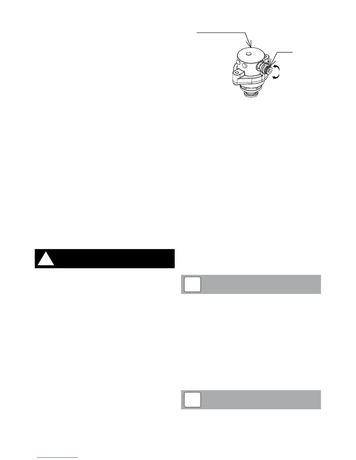
3. Remove the top (6kW) and front right (10kW and 16kW) casing
and loosen the plug on the automatic air vent located inside the
heat pump. Refer to Figure 4-3.
loosen
tighten
Auto air vent
Plug
Figure 4-3: Auto Air Vent
4. Ensure that the flexible filling loop is connected and that the
double check shut off valve connecting it to the water supply is
closed. A valve is open when the operating lever is in line with
the valve, and closed when it is at right angles to it.
5. Open the fill point valve.
6. Gradually open the double check valve from the water supply
until water is heard to flow.
7. When the needle of the pressure gauge is between 0.5 and 1.0
bar, close the valve.
8. Vent each radiator in turn, starting with the lowest one in the
system, to remove air.
9. Continue to fill the system until the pressure gauge indicates
between 0.5 and 1.0 bar. Close the fill point valve. The system fill
pressure (cold) should be 0.2 - 0.3 bar greater than the vessel
charge pressure – giving typical system fill pressures of approx
0.5 bar for a bungalow and 1.0 bar for a two storey house.
Refer to the Domestic Heating Design Guide for further
information if required.
10. Repeat steps 8 and 9 as required until system is full of water at
the correct pressure and vented.
11. Water may be released from the system by manually operating
the safety valve until the system design pressure is obtained.
12. Close the fill point and double check valves either side of the
filling loop and disconnect the loop.
13. Check the system for water soundness, rectifying where
necessary.
The air charge pressure may be checked using a tyre
pressure gauge on the expansion vessel Schraeder valve.
The vessel may be re-pressurised, when necessary, using
a suitable pump. When checking the air pressure, the water
in the heating system must be cold and the system pressure
reduced to zero.
NOTE
!
4.3 Pressure Relief (Safety) Valve Operation
Check the operation of the pressure relief (safety) valve as follows:
1. Turning the head of the valve anticlockwise until it clicks. The
click is the safety valve head lifting off its seat allowing water to
escape from the system.
2. Check that the water is escaping from the system.
3. Top-up the system pressure, as necessary.
The expansion vessel air pressure, system pressure and
operation of the pressure relief valve must be checked on
each service. Refer to Section 10.
NOTE
!