Section 6: Electrical Page 23
6.2 Terminal PCB Input/Output
Serial connections
Terminal Function Analogue Input Digital Input
1 - 2 - 3 Remote controller 1=S1, 2=S2, 3=GND
Wire length is
maximum 100m with
1mm² shielded cables
Analogue/Digital INPUTS
Table 6-2: Terminal PCB input/outputs
Terminal Function Analogue Input Digital Input
19 - 18 DHW remote contact
Voltage free contact
12V10mA
20 - 21 Configurable input -ON/OFF remote contact
28 - 29* Night mode - optional
30 - 31* Low tariff - optional
* Requires external timer
For details of how to access the parameter settings, refer to Section 9.3.
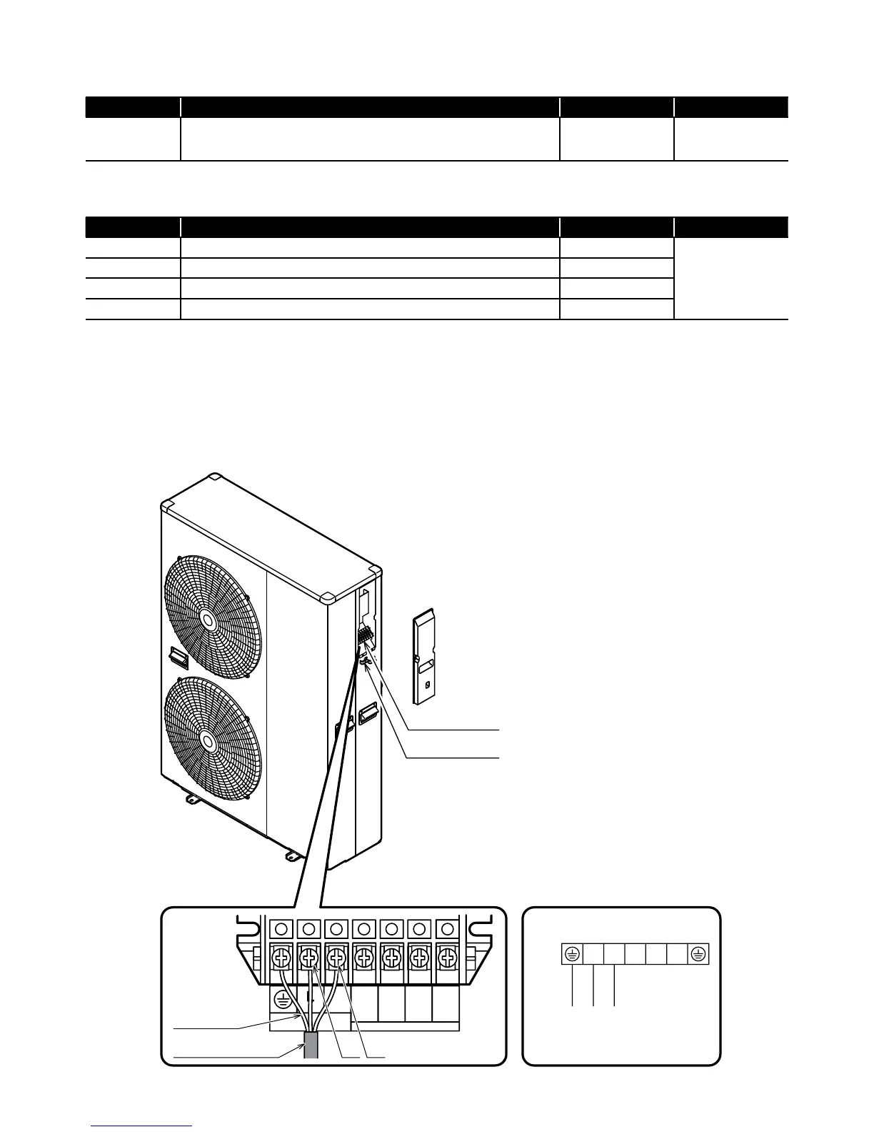
Terminal block
Cable clamp
Connection diagram
Unit side terminal
Power supply
Earth
N
)L( )N(
1 2 3
Earth wire
Power supply cord
)L( )N(
POWER
N
Do Not Use
Do Not Use
L
Figure 6-3: Power supply
6.3 Power Supply
Use a dedicated power supply with a correctly sized circuit breaker.
The final power supply connection must be made from a weatherproof
lockable isolator located outside the building.
The cable should be either armoured or run in a flexible conduit
between the isolator and heat pump.