Section 6: ElectricalPage 24
Cable and circuit breakers should be to EN Standards.
NOTE
!
Table 6-5: Power supply cable and breaker capacity
Model
Power supply cable (mm²)
Breaker
capacity
Maximum Minimum
HPID6 2.5 1.5 16A Class C
HPID10 4.0 2.5 20A Class C
HPID16 6.0 4.0 32A Class C
In the case of long cable runs, selection of correct cable must
be done in accordance with BS 7671 (IET Wiring Regulations)
NOTE
!
Strip ends of connecting cables in accordance with Figure 6-6.
Crimp terminals with insulating sleeves can be used if required
as illustrated in the diagram below for connecting the wires to the
terminal block. Stranded conductors shall not be soldered.
• Use a circuit breaker with a 3 mm clearance of air gap between
the contacts.
• Be sure to FULLY insert the cable cores into the proper position
of the terminal block.
• Faulty wiring may cause not only abnormal operation but also
damage to PCB board.
• Fasten each terminal screw securely.
• To check the connections are secure, pull the cable slightly.
10 mm 30 mm
Terminal block
Crimp terminal
Stripped wire :10mm
Sleeve
Crimp terminal
Sleeve
PCB(Terminal)
Figure 6-6: Stripping the cables
It is important that the cable is stripped back 10mm.
If shorter, it is possible to clamp down onto the insulation.
If longer, a short circuit may occur.
!
CAUTION
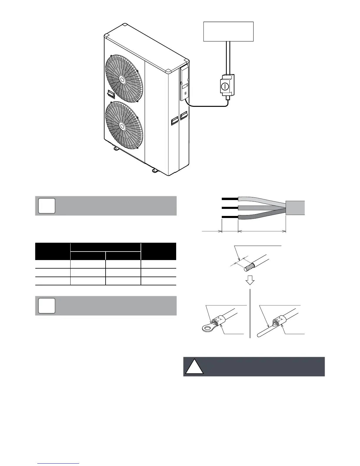
Lockable
isolator
Consumer
unit
Figure 6-4: Heat pump, isolator and consumer unit