Section 1: Introduction Page 5
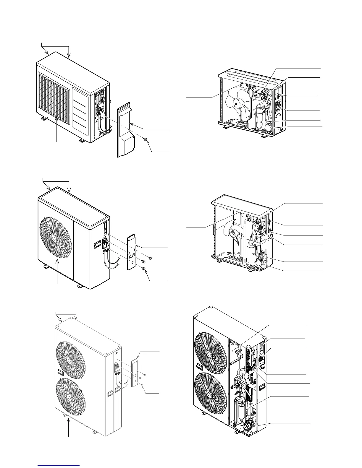
1.11 Heat Pump Components
Air inlet is located in the left and rear of the unit
Air outlet
Wiring cover
Screw
Air inlet is located in the left and rear of the unit
Air outlet
Wiring cover
Screw
Air inlet is located in the left and rear of the unit
Air outlet
Wiring cover
Screw
Terminal PCB
Auto-air vent
Terminal block
Pump
Compressor
Pressure relief valve
Main PCB
Main PCB
Terminal PCB
Terminal block
Pump
Pressure relief valve
Auto-air vent
Compressor
Terminal PCB
Pressure relief valve
Auto-air vent
Terminal block
Pump
Compressor
Main PCB
Figure 1-1: Main components (external) - 6kW
Figure 1-2: Main components (external) - 10kW
Figure 1-3: Main components (external) - 16kW Figure 1-6: Main components (internal) - 16kW
Figure 1-5: Main components (internal) - 10kW
Figure 1-4: Main components (internal) - 6kW