Section 11: Fault Finding Page 55
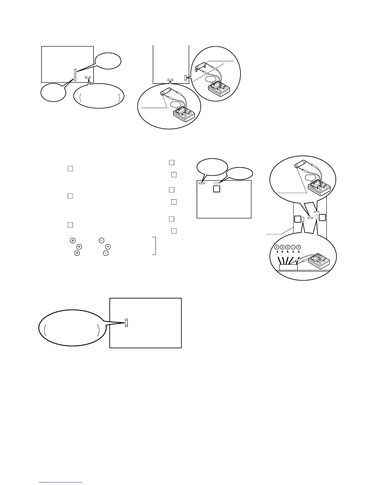
Figure 11-3: Continuity of current Fuse on the Main PCB
Figure 11-4: Voltage of Fan motor on the Main PCB
Figure 11-5: Continuity of current Fuse on the Main PCB
Main
PCB
Fuse CF1
(250V T30A)
0Ω
Fuse CF3
(250V 3A)
0Ω
Fuse CF4
(250V 3A)
Main
PCB
Fuse CF3
(250V 3A)
Fuse CF1
HPID6 : 250V 15A
HPID10 : 250V 25A
[HPID16][HPID6 and HPID10]
14
11
BL Y W B R
LOWER:
Fuse CF6
UPPER:
Fuse CF7
(250V T3.15A)
0Ω
Fan motor
Main
PCB
18
Fan motor
Main
PCB
Fuse CF7
(250V T3.15A)
Measure voltage between the connector pins of connector
11
.
Connector
11
shall be checked during heating operation.
Measure voltage as follows without taking off the connector
11
.
Measure voltage between the connector pins of connector
18
.
Connector
18
shall be checked during heating operation.
Measure voltage as follows without taking off the connector
18
.
Measure voltage between the connector pins of connector
14
.
Connector
14
shall be checked during heating operation.
Measure voltage as follows without taking off the connector
14
.
Between red
and black
, approx. DC200~370V
Between yellow
and black
, approx. DC3~7V
Between white
and black
, approx. DC15V
Main PCB is normal
LOWER Fan motor (HPID16)
Fan motor (HPID6 and HPID10)
UPPER Fan motor (HPID16)
[HPID16][HPID6 and HPID10]
Main
PCB
Fuse CF6
HPID6: 250V 15A
HPID10: 250V 25A
11.6 Error Codes and PCB Alarm Figures and Tables