Section 11: Fault FindingPage 56
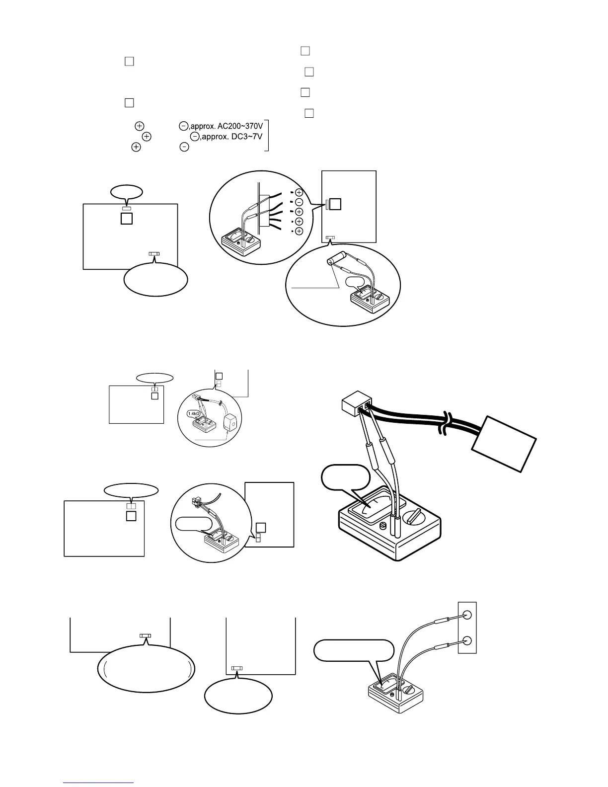
Figure 11-6: Voltage of pump on the Main PCB
Figure 11-7: Resistance of the 4way valve coil
Figure 11-8: Resistance of the defrost heater
Figure 11-9: Continuity of current fuse on the Main PCB
Figure 11-10: Resistance of the compressor overheat protection
relay
Figure 11-11: Voltage of humidity sensor
17
Pump
Fuse CF2
(250V T3.15A)
Main
PCB
Between white and black
Between brown and black
Between red and black
,approx. DC15V
Main PCB is normal
W
B
R
BR
BL
13
Fuse CF2
(250V T5A)
0Ω
Pump
Main
PCB
[HPID16]
[HPID6 and HPID10]
Measure voltage between the connector pins of connector
17
.
Connector
17
shall be checked during heating operation.
Measure voltage as follows without taking off the connector
17
.
Measure voltage between the connector pins of connector
13
.
Connector
13
shall be checked during heating operation.
Measure voltage as follows without taking off the connector
13
.
Pump (HPID6 and HPID10)
Pump (HPID16)
8
4-way valve coil
Main
(PCB
10
4way valve coil
Main
PCB
Take off the connector and check the resistance 4way valve coil.
[HPID16]
[HPID6 and HPID10]
9
260~300Ω
Main
PCB
11
Main
PCB
Defrost heater
[HPID16]
[HPID6 and HPID10]
PCB
(Main)
PCB
(Main)
Fuse CF2
0639U : 250V T3.15A
1039U : 250V T3.15A
Fuse CF2
(250V T5A)
[1639U][0639U,1039U]
0Ω
OHR
0.147~9.80V
17
18
Humidity
Sensor
COM