Section 3: Installation InformationPage 14
3.10 Before you Commission
3.10.1 Flushing and Corrosion Protection
To avoid the danger of dirt and foreign matter entering the heat pump
the complete heating system should be thoroughly flushed out – both
before the heat pump is operated and then again after the system
has been heated and is still hot.
This is especially important where the heat pump is installed as a
replacement for a boiler on an existing system.
In this case the system should be first flushed hot, before the old
boiler is removed and replaced by the heat pump.
For optimum performance after installation, this heat pump and
the central heating system must be flushed in accordance with the
guidelines given in BS 7593:2006 ‘Treatment of water in domestic hot
water central heating systems’.
This must involve the use of a proprietary cleaner, such as Sentinel
X300 or X400, or Fernox Restorer.
After flushing, a suitable thermal fluid should be used (such as
Sentinel R600) specifically designed for use in air source heat pump
installations. This provides long term protection against corrosion
and scale as well as the risk of the freezing in the external section of
the heating system (i.e. the flexible hoses, condenser and circulating
pump within the heat pump casing) in the event of power failure
during winter months.
In order to avoid bacterial growth, due to the lower system operating
temperatures, a suitable Biocide (such as Sentinel R700) should also
be used in conjunction with the thermal fluid.
Both the thermal fluid and biocide should be added to the system
water when finally filling the heating system.
Alternatively, Fernox HP5C can be used (or HP15C for greater frost
protection).
This is a suitable thermal fluid that already contains a suitable
biocide.
Full instructions on the correct use of thermal fluids and biocides are
supplied with the products, but further information can be obtained
from either www.sentinel-solutions.net or www.fernox.com.
Failure to implement the above guidelines by fully flushing the system
and using a suitable thermal fluid and biocide corrosion inhibitor will
invalidate the heat pump product guarantee.
Grant Engineering (UK) Limited strongly recommends that a
Grant MagOne in-line magnetic filter/s (or equivalent*) is fitted
in the heating system pipework. This should be installed and
regularly serviced in accordance with the filter manufacturer’s
instructions.
* As measured by gauss. The MagOne magnetic filter has a gauss
measurement of 12000.
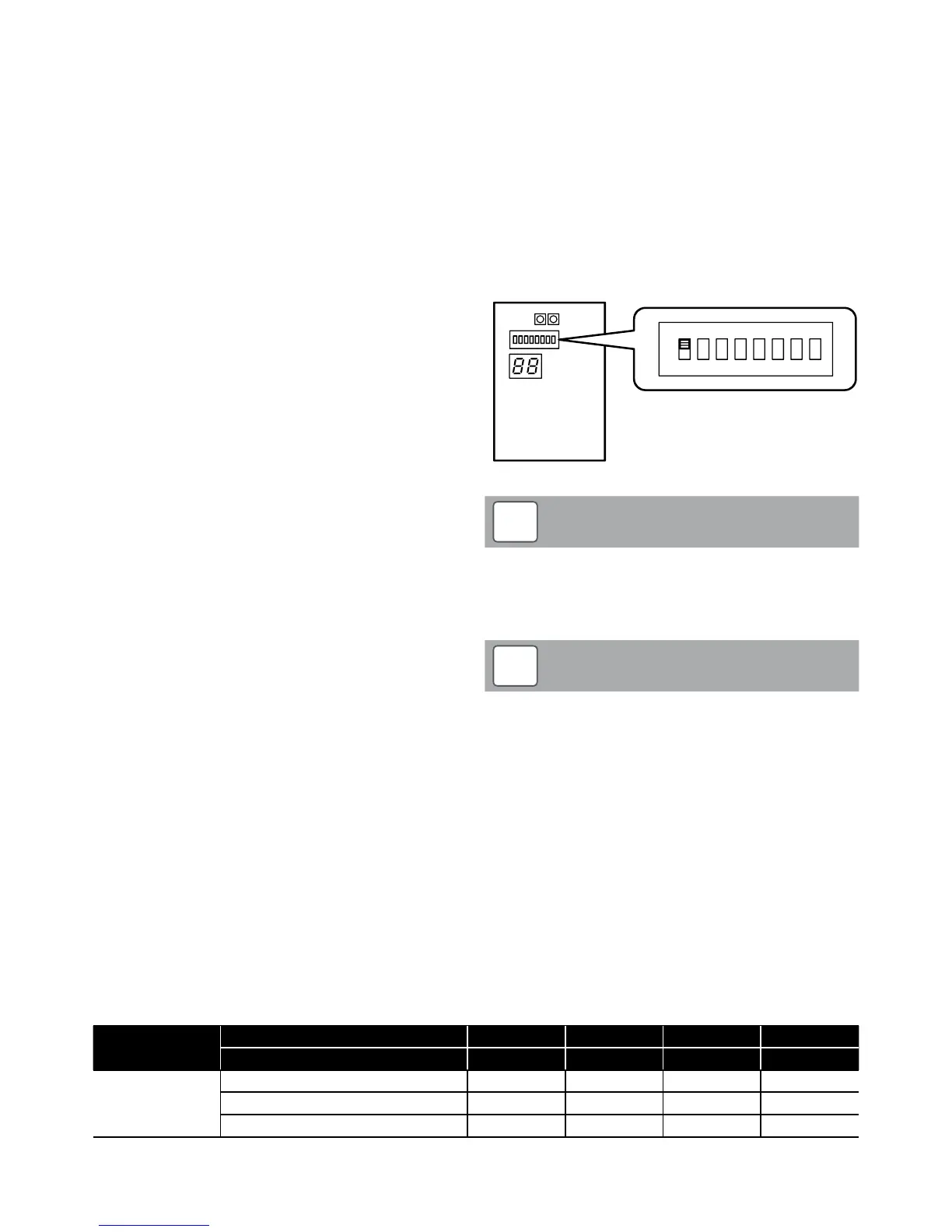
3.10.2 Anti-freeze function setting
This function is factory set to ON, i.e. DIP SW1 is set to ON (up
position).
With the frost protection function set to ON, it will operate as
described in Sections 8.4.1, 8.4.2 and 8.4.3.
Table 3-6: Antifreeze concentration
% Monoethylene glycol inhibitor 10% 20% 30% 40%
Freezing temperature* -4°C -9°C -15°C -23°C
Correction
factor
Capacity 0,996 0,991 0,983 0,974
Power absorbed 0,990 0,978 0,964 1,008
Pressure drop 1,003 1,010 1,020 1,033
* The temperature values are indicative. Always refer to the temperatures given for the specified product used.
For details of how to access the parameter settings, refer to Section 9.3.
This function is not required if ethylene glycol is used in the heating
system water to prevent freezing.
If a suitable concentration of ethylene glycol (heating system
antifreeze) is used in the system water. Refer to Table 3-6 for suitable
antifreeze concentrations or follow the manufacturer’s instructions
supplied with the antifreeze.
If not required, frost protection function can be disabled as follows:
• Remove the wiring cover at the right hand end of the heat pump.
Refer to Figure 6-1.
• Set DIP SW1 to OFF (down position). Refer to Figure 3-7.
• Replace the wiring cover and secure in place with the screws
provided.
Terminal PCB
ON
1
OFF
DIP SW. position
2 3
4
5
6 7 8
Figure 3-7: Anti-freeze function setting
Dip switch positions:
Up: ON
Down: OFF
Refer to Sections 8.4.1, 8.4.2 and 8.4.3.
NOTE
!
Even with DIP SW1 set to OFF, to prevent the circulating pump
operating for frost protection it will also be necessary to reset
four of the factory set frost protection control parameters to
the ‘disabled’ setting. Refer to Table 3-8.
NOTE
!
To do this, use the remote controller as follows (refer to Section 9.1
page 46):
First access the Installer level:
1. Press and hold the ‘Menu’ (3) and the ‘-‘ and ‘+’ (6) buttons
together for 3 seconds to enter the installer level.
2. “InSt” parameter number “00 00” and parameter value “----“ will
be shown on the display. The first two digits of the parameter
number will be blinking.
Then, access the Service level:
1. Use the ‘Up’ and ‘Down’ (8) buttons to change these first two
digits to 99 and then press the ‘+’ button.