Motor
HW
HTG
Blue
Green/Yellow
Motor
Blue
Green/Yellow
Orange
Orange
Brown
Brown
17
18
19
20
21
22
23
24
25
1
2
3
4
5
6
7
8
11 12
13
14
15 16
Grey
Grey
Orange (Yellow)
Grey (Red)
Orange (Blue)
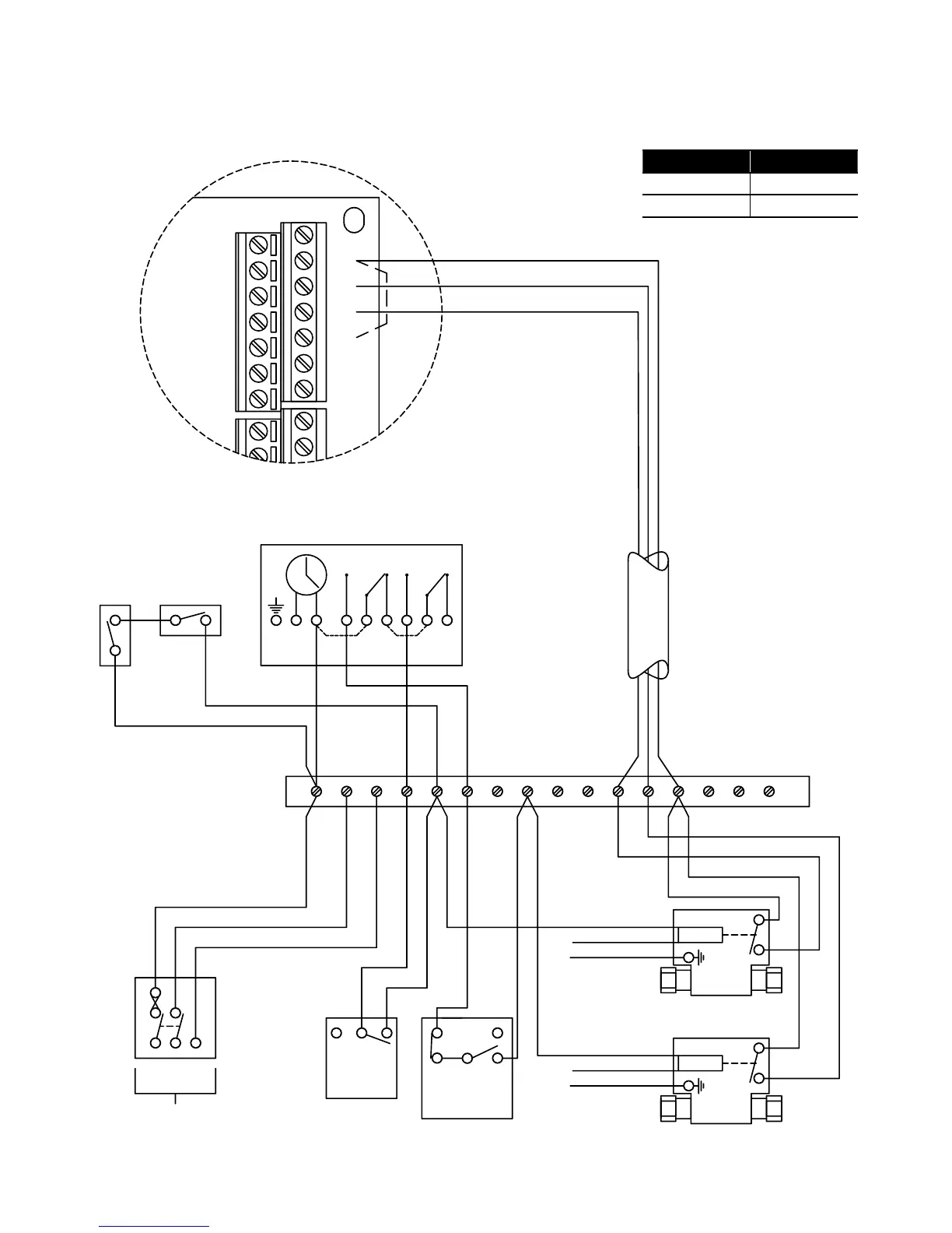
4 Core ( 3 + E )
Volt free connections
from Heating and Hot
Water Zone Valves to
Terminals 18 - 20 on
ASHP Terminal PCB
Link
Dual Limit &
Cylinder Stat
2
C
1
HW ON
N L 1 2
3
4
Horstmann H21 Series 21
E
COMMON
HW OFF
CH ON
COMMON
CH OFF
LINK LINK
Terminals
18 and 19 Hot water
20 and 21 Heating
The control system shown in this diagram ensures that there can be no demand for space heating and hot water at the same time.
In order to achieve this type of operation, the programmer MUST NOT have a built-in connection between the live connection
(driving the timer) and the two programmer switches.
The programmer shown in this diagram is an example of one that meets this requirement, as the installer is required to fit links
between the mains live and the programmer swithces for mains voltage systems.