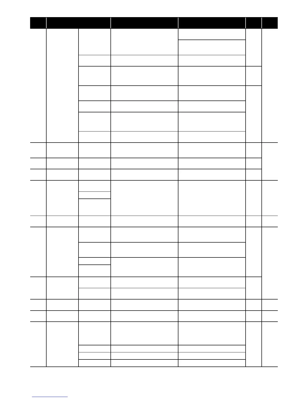
Section 11: Fault FindingPage 52
Error
code
Error Method of check Troubleshooting
Figure/
table
Error
reset
A5
Abnormal
revolution of
compressor
Unreasonable
operation under/
overload
Check the place of installation (blockage
of air inlet & outlet )
Check the excess gas
Ensure the installation position to avoid
blockage of air inlet & outlet
-
Manual
If excess gas is observed, collect all
refrigerant once, then recharge with
prescribed mass
Drop of power
voltage
Check the power voltage
(230V)
Confirm the power supply voltage
(230V)
Fuse CF6
HPID6: 250V 15A
HPID10 : 250V
25A
Check the electric continuity
Fuse CF6 by tester
If CF6 is blown, Main PCB should be
replaced
Figure
11-5
Clogged the water
Pump and/or
water circuit
Check the Pump and water circuit
Remove the blockage, then restart
operation
Drop of power
voltage
Check the power voltage
(230V) during operation
Confirm the power supply voltage
(230V)
Momentary stop
of power
(In case of
lightning)
- Restart operation
Compressor or
Main PCB
Other than described above Compressor should be replaced
A6
Suction
temperature
sensor error
Sensor, Temp.
Suction
Check the resistance by tester
If the sensor is faulty, it should be
replaced
Figure
11-14
Auto
A7
Defrost tem
sensor error
Sensor, Temp.
Defrost
Check the resistance by tester
If the sensor is faulty, it should be
replaced
Figure
11-14
A8
Discharge temp.
sensor error
Sensor, Temp.
Discharge
Check the resistance by tester
(*1)
If the sensor is faulty, it should be
replaced
Figure
11-13
C1
Upper fan motor
error
(HPID16)
Fuse CF7
(250V T3.15A)
Check the electric continuity
Fuse CF7 by tester
If CF7 is blown, Fan motor and CF7
should be replaced
If CF7 is not blown, check the voltage of
Fan motor
If the voltage is normal, Fan motor should
be replaced
If the voltage is abnormal, Main PCB
should be replaced
Figure
11-4
Auto
Fan motor (*2)
Main PCB
C2
Outdoor temp.
sensor error
Sensor, Temp.
Outdoor
Check the resistance by tester
If the sensor is faulty, it should be
replaced
Figure
11-12
Auto
C3
Lower Fan motor
error
(HPID16)
Fan motor error
(HPID6 and
HPID10)
Fuse CF6
(HPID16: 250V
T3.15A)
Check the electric continuity of Fuse CF6
by tester
If CF6 is blown, it should be replaced
Figure
11-4
Manual
Fuse CF7
(HPID10: 250V
T3.15A)
Check the electric continuity of Fuse CF7
by tester
If CF7 is blown, it should be replaced
Fan motor
Check the voltage of Fan motor by tester
If the voltage is normal, Fan motor should
be replaced
If the voltage is normal, Main PCB should
be replaced
Main PCB
C4
Rise of
temperature
(above 110°C) of
Main PCB
Mis-installation
Check the place of installation (blockage
of air inlet & outlet)
Ensure the installation position to avoid
blockage of air inlet & outlet
-
Sensor, Temp.
Main PCB
- Main PCB should be replaced
C5
Main PCB sensor
error
Sensor, Temp.
Main PCB
- Main PCB should be replaced - Auto
C6 Main PCB error Main PCB - Main PCB should be replaced -
Power
OFF
C7
Controller PCB
serial error
Mis wiring or rare
contact [Main
PCB - Controller
PCB connecting
cable]
Check the wiring connection and rare
contact
After correcting mis wiring, restart
operation
- Auto
Controller PCB Other than described above Controller PCB should be replaced
Main PCB Other than described above Main PCB should be replaced
Earth wire - Check if earth wire is properly installed
(*1) In case of detecting open circuit of the discharge temperature sensor, error display appears 10 minutes after start operating.
In case of detecting short circuit of the discharge temperature sensor, error display appears immediately.
(*2) When checking fan motor and/or pump, turn OFF the power supply completely and check at their terminal or connector.