Installation
110 Planning and Installation Manual
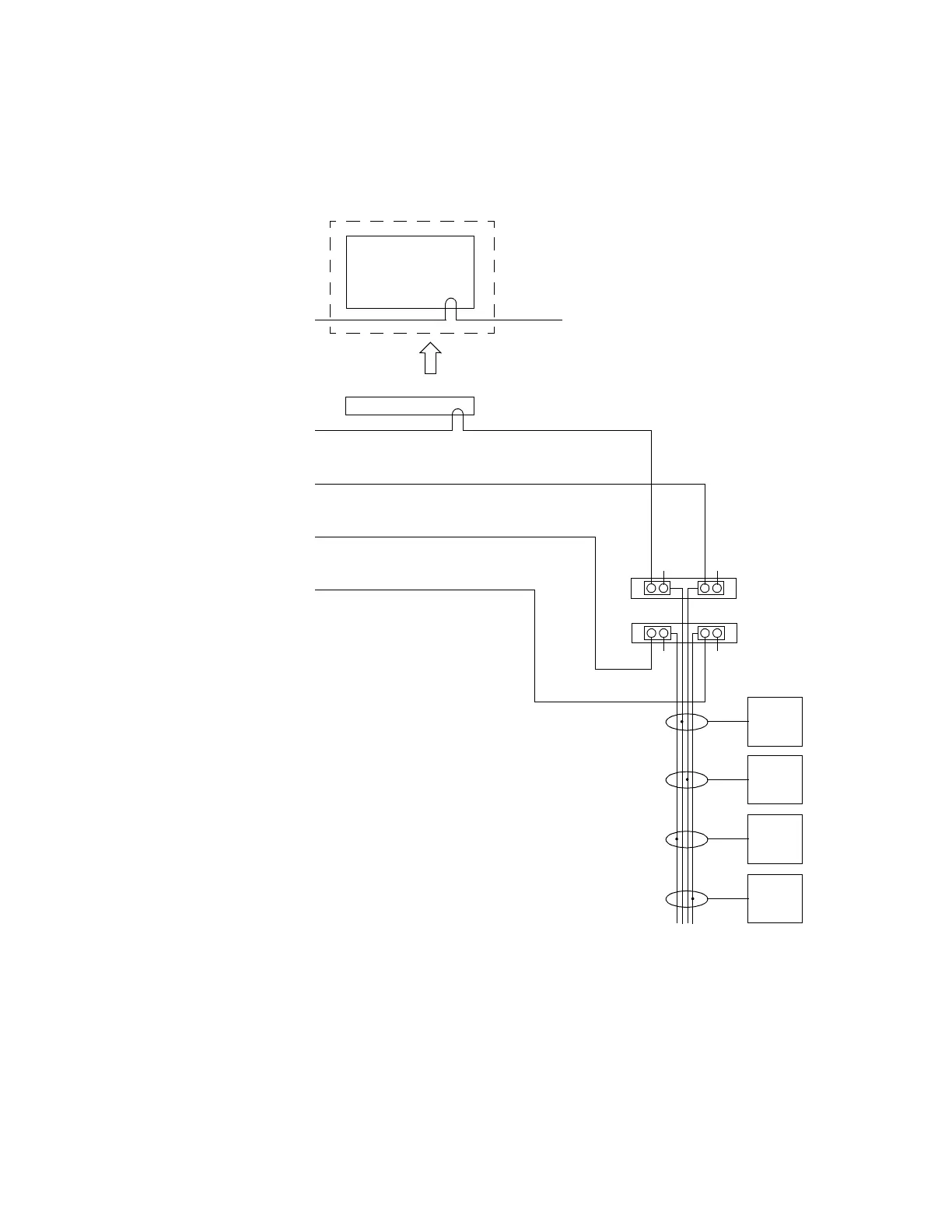
DV-33128 / DV-33256 with Multi Sync References
Figure 49.
This arrangement is similar to that described on the previous page,
except that all four possible sync references are used.
For a discussion concerning which sync reference should be connected
to the control system, see Sync Connection to Control System on page 109.
Jupiter
Sync 1
Output
board(s)
on SL1
Output
board(s)
on SL2
Output
board(s)
on SL3
Output
board(s)
on SL4
Sync Lines
Sync 2
Sync 3
Sync 4
SMS MCPU
Sync 1
or
Encore SCB
OR
Sync Redundant switch = Off
Sync
1
21
Primary NR-33000
Secondary NR-33000
TT
43
TT
 Loading...