Sync Reference Connections
Planning and Installation Manual 111
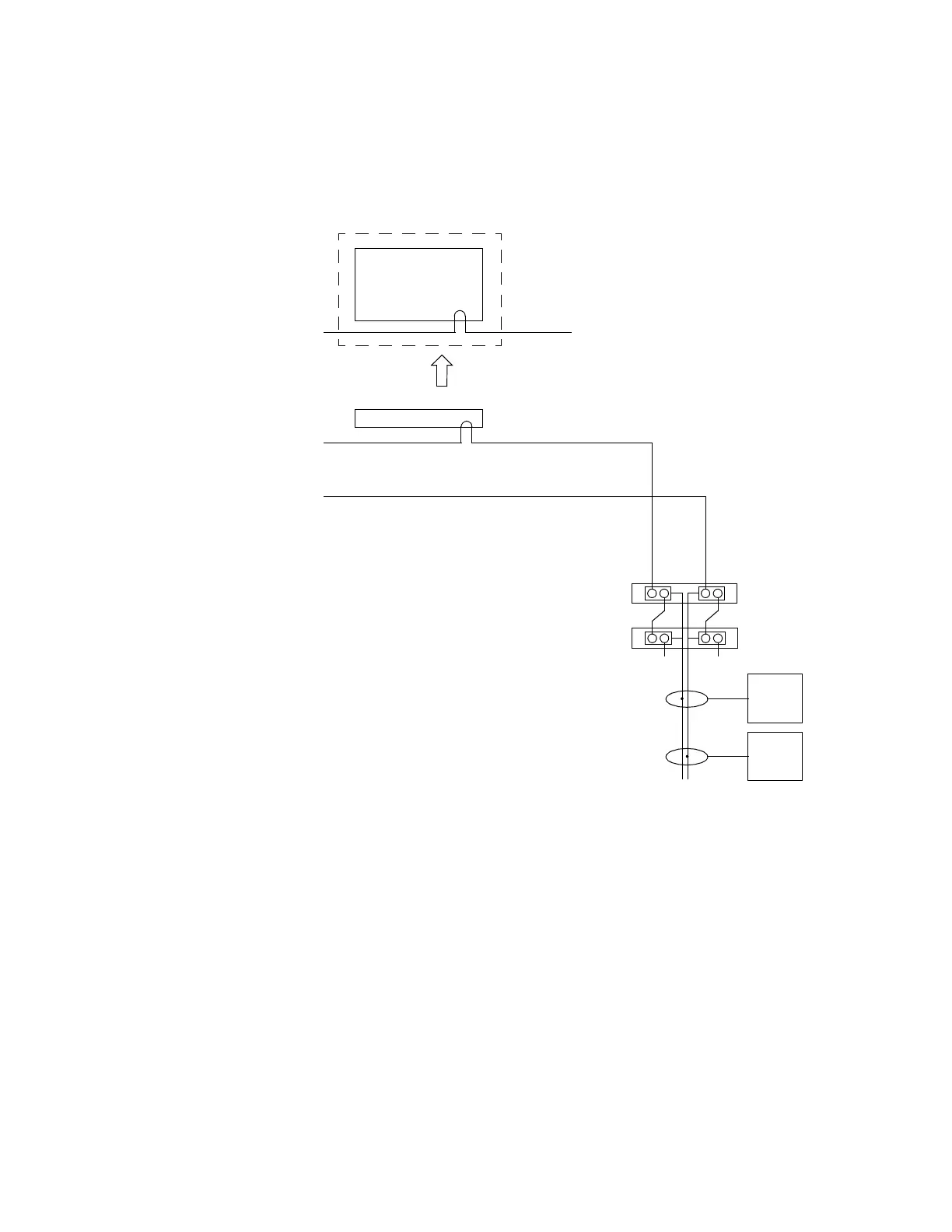
DV-33128 / DV-33256 with Sync Redundant NR Operation
Figure 50.
For NR-33000 redundant operation, one (or two maximum) sync refer-
ences are looped from the Primary to the Secondary boards. If the
Primary board fails the system will switch automatically to the Sec-
ondary board. Note that in this arrangement Sync Bus 1 is always com-
bined with Sync Bus 3 and Bus 2 combined with Bus 4. When
configuring the output boards, only “Bus 1” and “Bus 2” are valid selec-
tions.
For a discussion concerning which of the two sync references should be
connected to the control system, see Sync Connection to Control System
on page 109.
Jupiter
Sync 1
21
Primary NR-33000
Secondary NR-33000
Output
board(s)
on SL1
Output
board(s)
on SL2
Sync Lines
Sync 2
SMS MCPU
Sync 1
or
Encore SCB
OR
Sync
1
TT
43
Sync Redundant switch = On
 Loading...