Output Board Configuration
Planning and Installation Manual 123
Output Board Configuration
This adjustment applies to systems with more that one sync reference.
Each output board provides a block of 32 outputs and by factory default
each block is assigned to sync reference 1. If additional references are
used, DIP switch S5 on each output board is used to assign the board to
one of four possible sync lines.
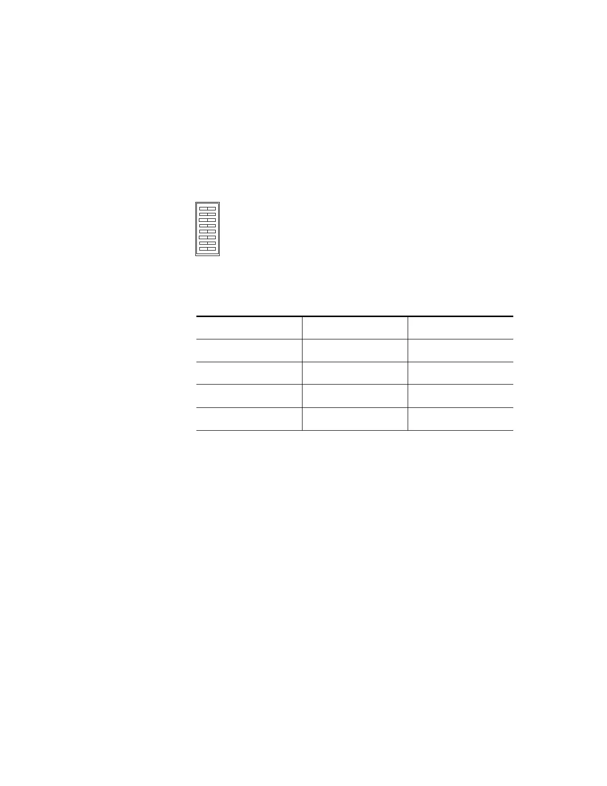
Figure 60.
Ta b l e 21 .
Sync line Sync Sel A switch Sync Sel B switch
1 Closed Closed
2OpenClosed
3ClosedOpen
4 Open Open
SYNC SEL A
SYNC SEL B
AUTO RCLK
CLOSED OPEN
 Loading...