Installation
154 Planning and Installation Manual
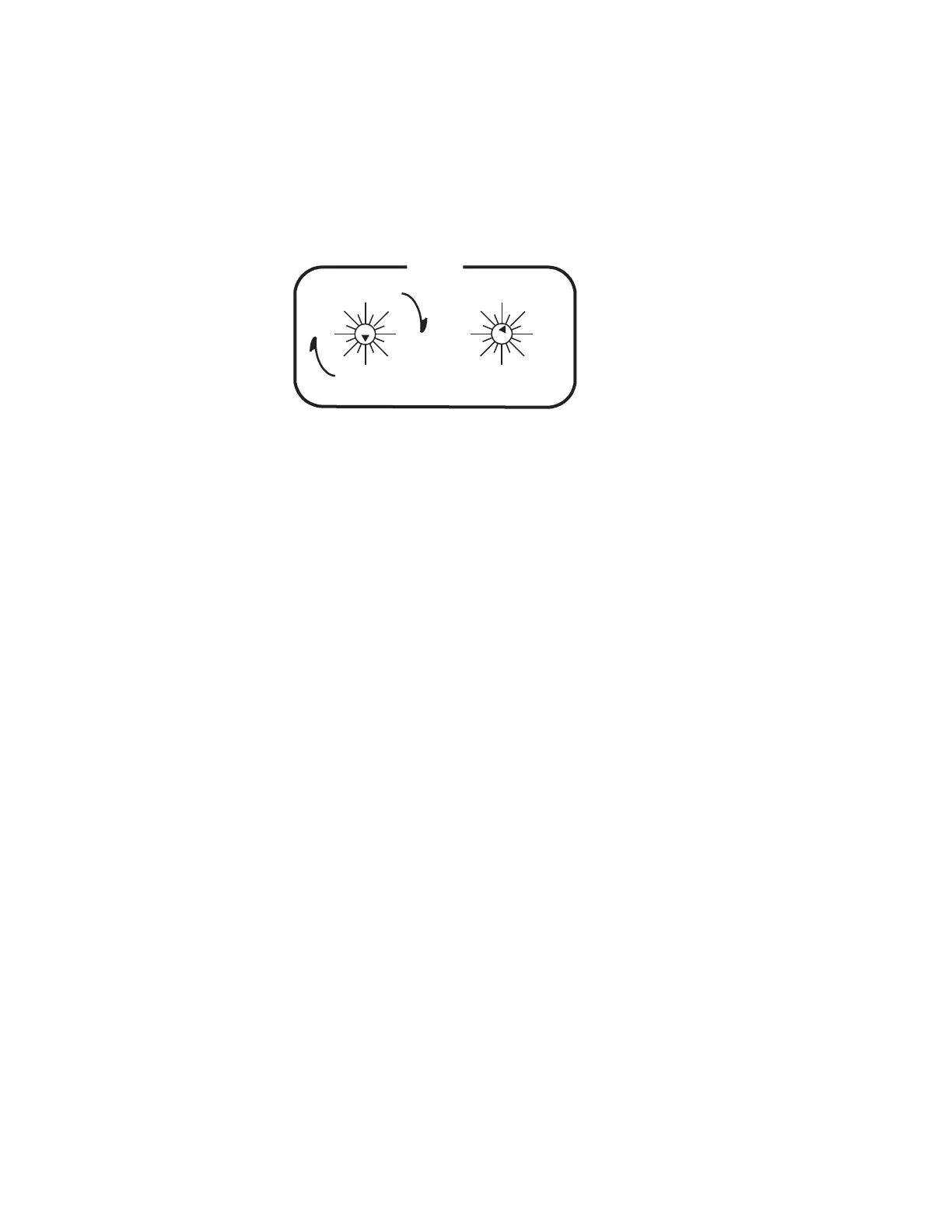
b. On DV-33512 units only, the rear-panel rotary Level switch must
be set to “Ultra” crosspoint bus, Level 1; i.e., the Super/Ultra
rotary switch must be pointed straight down to “0” and the
adjacent rotary switch must point at “1.” These restrictions do
not apply to DV-33128 and DV-33256 units. See Figure 87.
Figure 87.
3. On DV-33512 units only, a crosspoint bus cable must be installed
between the power supply chassis and the main chassis.
If there is more than one DV-33512 in the system, the crosspoint bus
must be daisy-chained between units.
The crosspoint bus must be terminated at the farthest point from the
controlling Broadlinx board.
This connection is shown on page 102.
The crosspoint bus cable is described on page 149.
4. Install LAN components as described beginning on page 155.
5. Refer to the SMS 7000 or Encore documentation for control system
configuration details.
0
1
2
3
4
5
6
7
8
9
10
11
12
13
14
15
64
0
16
32
48
80
96
112
0
16
32
48
64
80
96
112
LEVEL
SUPER
ULTRA
 Loading...