Planning and Installation Manual 167
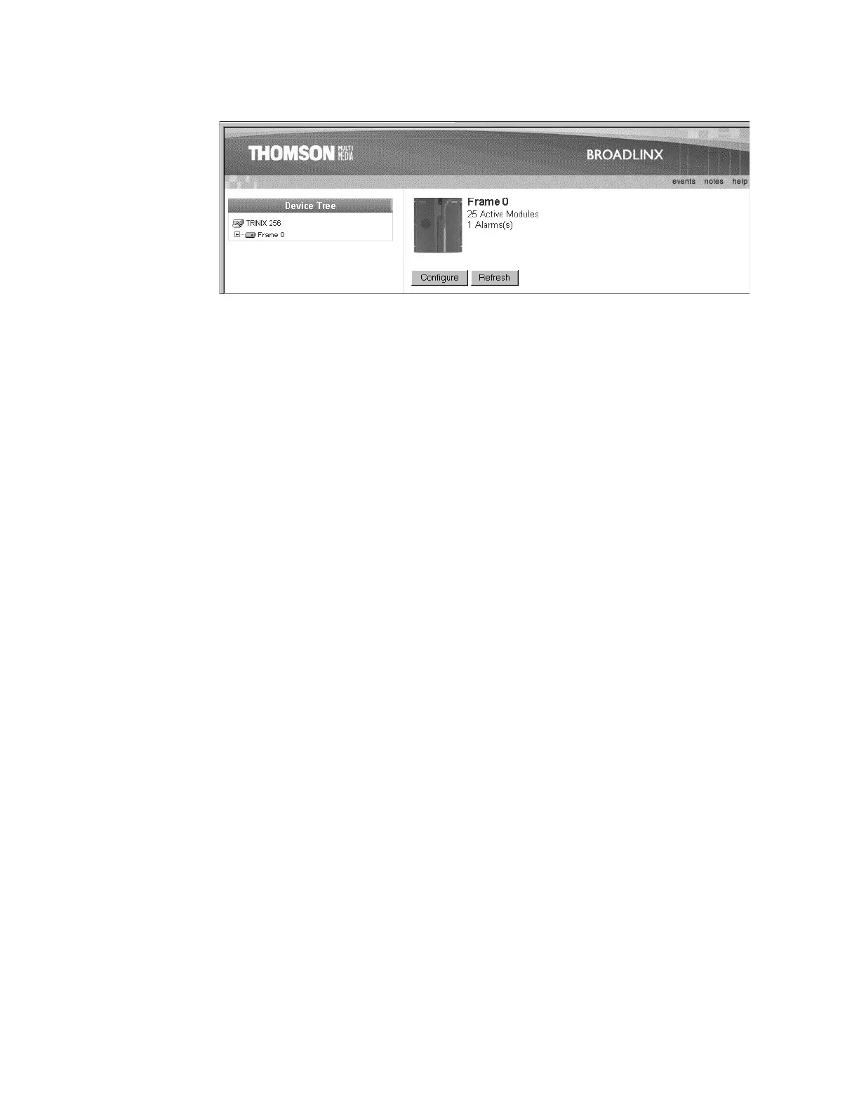
Figure 95.
In this example, “Device Tree” is the System Description. This name
can be modified if desired (as described on page 174). The list below
the System Description can be expanded to show all system PC
boards and modules available for Broadlinx communication.
The graphic of the router front panel shows the status of the master
alarm (green or red dot).
For a discussion of Frame Numbers, see page 146.
Note The Broadlinx displays do not update themselves automatically. Use the
“Refresh” button in the Broadlinx window to update screens. You may
be asked “Repost Form data?”; answer Yes.
To return to this page at any time, use the Internet Explorer
“Refresh” button.
 Loading...