Broadlinx
168 Planning and Installation Manual
Checking Hardware Status
1. Connect to the router following the procedure just described.
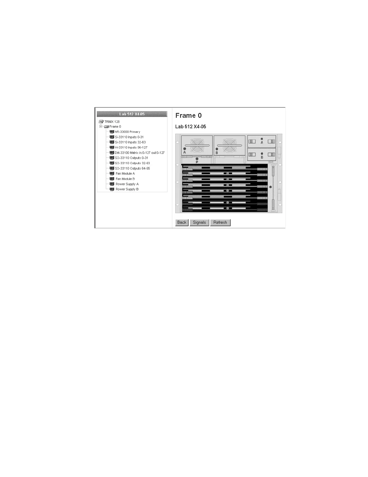
2. Click on the graphic of the router front panel. A line drawing of the
Trinix chassis will appear (similar to Figure 96).
Figure 96.
In this example, all modules and boards show a green dot meaning
that operation is normal.
3. Click on a module or board to check its condition. See Figure 97.
You can click either on the name in the list or on the graphic.
For DV-33512 routers, the SR-33500 Sync Reference board and the
RP-33500 Rear Panel must be selected from the list (because these
boards on located on the rear panel).
 Loading...