Protected Paths
Planning and Installation Manual 65
The numbers shown here correspond to the connector numbers used
during router configuration (but not, in most cases, to the actual silk
screen number on the rear panel itself since the silk screen numbers
only run from “1” to “32.”)
In Jupiter-controlled systems, the “Name” corresponds to the “logical
input/output name” and the number corresponds to the “physical”
input/output number.
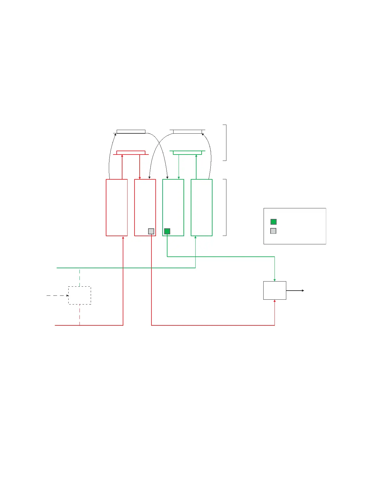
Figure 33. Example of protected paths for DV-33256 router
Input/Output
boards
DM-33100
Matrix boards
Splitter
Combiner
Input 1Output 1
Primary path
Secondary path
Output 128Input 128
Output Status
Signal OK, driver ON
Output assigned to
protected path, driver OFF
protected path, driver OFF
Inputs
1-128
Outputs
1-128
Outputs
129-256
Inputs
129-256
 Loading...