Commissioning
Page 34 of 111
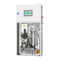
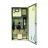
5.5 WMPH
Check points relevant for the installation of the WMPH system are described in this
section.
• Verify that the check list found in the section 7. Appendix in the installation manual
has been filled out.
• Check the power supply connections are as specified in the Electrical Drawings.
• Check protective earth is connected
• Cut off the small rubber tip on top of the manometer. However, do not remove the
black rubber part.
• Only switch on the pump if the front cover has been properly attached.
• Check the rollers are correctly fitted and fastened.
• Check the hose and rollers are thoroughly greased with silicone grease.
• Check the direction of rotation corresponds to the inlet/outlet connections. Inlet
must be at the top connection and outlet must be at the bottom connection. Please
refer to Diagram inside the junction box of the motor to change the direction of
rotation.
• Note: The pump pressure should be as low as possible during operation to maximise
the lifetime of the hose. Pressure and flow can be adjusted by means of the safety
valve/pressure regulating valve in the WMPH cabinet.
Recommended pressure: 0.8…2.0 bar.
 Loading...