GREENWORKSTOOLS.COM GREENWORKSCOMMERCIAL.COM
17
2021-03-18
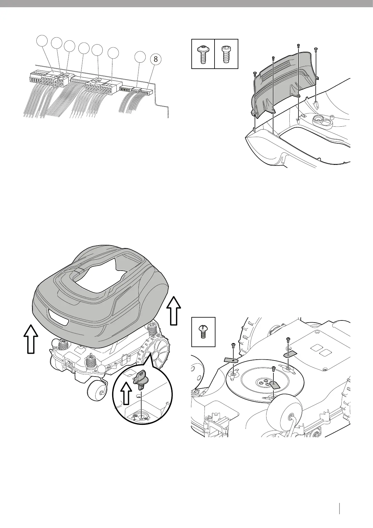
4.2. MAIN BOARD CONNECTIONS
Right wheel motor assy connection
Charging connector assy connection
Battery connection
Communication board connection
Cutting motor assy connection
Left wheel motor assy connection
Lift sensor assy connection
Loop sensor assy connection
4.3. DISASSEMBLING THE BODY
Press the STOP button and remove the safety key.
Remove the body from the chassis by lifting the body one corner
at a time while holding the chassis in place.
4.4. REPLACING THE BODY REAR ASSY
Disassemble the body (see section 4.3).
Unscrew the two type 1 fasteners and the two type 2 fasteners
that secure the body rear assy to the lower chassis.
Remove the old body rear assy.
Fit the new body rear assy on the two tabs.
Insert two type 1 fasteners in the upper holes and two type 2
fasteners in the lower holes and tighten to the correct torque (see
section 3).
Assemble the body (see section 4.21).
4.5. REPLACING THE CUTTING BLADES
WARNING!
Press the STOP button and remove the safety key before replacing
blades and wear protective gloves.
CAUTION:
Replace all three blades and screws as a set at the same time.
Turn the mower upside down.
Unscrew three type 3 fasteners using a straight slot or cross tip
screwdriver.
Remove the blades and the screws.
Screw in the new blades using new type 3 fasteners.
Check that the blades pivot freely.
X2 X2
X3
Note: If the magnet falls out, reinsert it into the chassis with
dot/line (or marking) visible.
1
2
3
4
5
6
7
8
1
2
1
2
3
4
5
6
1
2
3
4
5
5
6
4
3
2
1
7