GREENWORKSTOOLS.COM GREENWORKSCOMMERCIAL.COM
20
2021-03-18
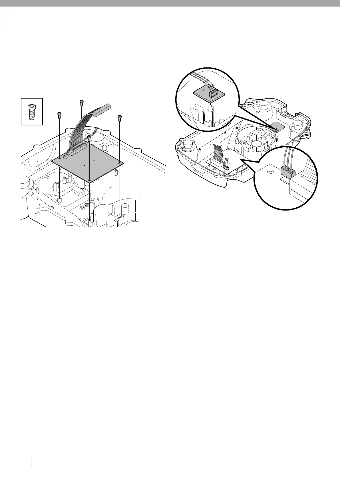
4.11. REPLACING THE COMMUNICATION BOARD
Disassemble the body (see section 4.3).
Disassemble the chassis (see section 4.10).
Turn the upper chassis upside down.
Carefully disconnect the collision sensor cable from the
communication board.
Unscrew the four type 2 fasteners that secure the communication
board to the upper chassis.
Remove the old communication board and fit the
newcommunication board.
Note: Only touch the edges of the board.
Insert four type 2 fasteners and tighten to the correct torque (see
section 3).
Connect the collision sensor cable to the communication board.
Assemble the chassis (see section 4.20).
Assemble the body (see section 4.21)
Connect to service portal (A3S) and register the replacement of
the Communication board.
4.12. REPLACING THE COLLISION SENSOR ASSY
Disassemble the body (see section 4.3).
Disassemble the chassis (see section 4.10).
Turn the upper chassis upside down.
Disconnect the collision sensor cable from the communication
board.
Note: Always pull the connector and not the cable.
Cut the cable ties holding the collision sensor cable to the upper
chassis.
Remove the collision sensor board by carefully bending up the
snap fasteners and lifting out the collision sensor circuit board.
Fit the new collision sensor circuit board under the snap
fasteners.
Note: Only touch the edges of the board.
Connect the collision sensor cable to the communication board.
Secure the collision sensor cable to the upper chassis using type
4 fasteners (see section 3).
Assemble the chassis (see section 4.20).
Assemble the body (see section 4.21).
X4
1
2
3
4
5
1
2
3
4
5
6
7
8
9
10
11
6
7
8
9
10
11