GREENWORKSTOOLS.COM GREENWORKSCOMMERCIAL.COM
23
2021-03-18
4.17. REPLACING THE WHEEL MOTOR ASSY
Disassemble the body (see section 4.3).
Disassemble the chassis (see section 4.10).
Disconnect the wheel motor cable from the main board.
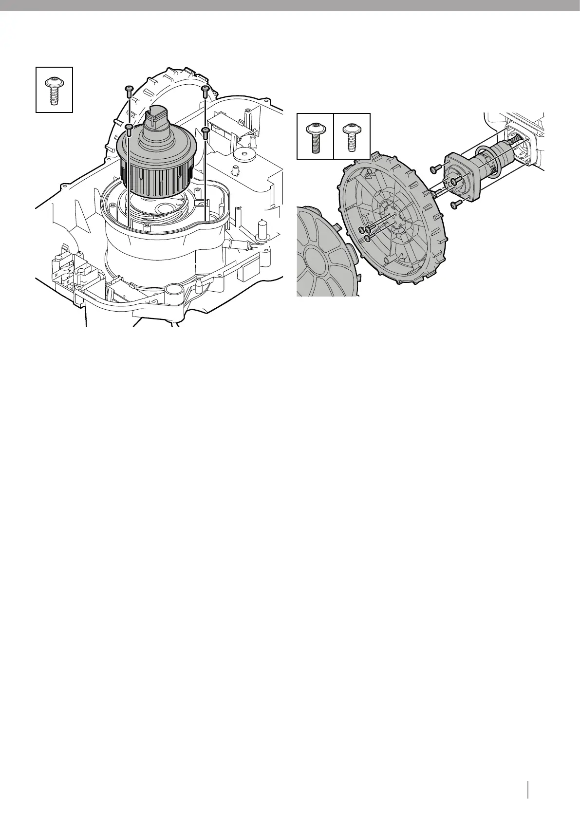
Remove the hub cap using a slotted screwdriver.
Unscrew the three type 4 fasteners that secure the wheel and
remove the wheel.
Unscrew the four type 1 fasteners that secure the wheel motor to
the lower chassis assy.
Remove the old wheel motor assy.
Fit the old wheel motor O-ring and the new wheel motor assy into
the chassis.
Insert four type 1 fasteners and tighten to the correct torque (see
section 3).
Connect the wheel motor cable to the main board.
Fit the wheel and insert three type 4 fasteners and tighten to the
correct torque (see section 3).
Fit the hub cap onto the wheel.
Assemble the chassis (see section 4.20).
Assemble the body (see section 4.21).
4.18. REPLACING THE CHARGING CONNECTOR ASSY
– REGULAR CUT
1 Disassemble the body (see section 4.2).
2 Disassemble the chassis (see section 4.9).
3 Disconnect the charging connector cable from the main board by
0 pressing down on the catch on the top of the connector and
0 pulling out from the main board.
Note: Always pull the connector and not the cable.
4 Cut the cable ties holding the charging connector cable to the
0 lower chassis. Unscrew the type 4 fastners holding the charging
0 connector.
5 Lift out the old charging connector assy and fit the new charging
0 connector assy.
Remove the old height adjustment housing sealing strip and
discard it.
Cut the cable ties holding the cutting motor cable to the lower
chassis.
Lift out the old cutting motor assy.
Disconnect the cutting motor cable from the main board.
Fit the new cutting motor assy.
Secure the cutting motor cable to the height adjustment housing
using one type 5 fastener.
Fit the height adjustment housing or the lower chassis.
Insert the new height adjustment nut assy sealing strip and add
silicone.
Note: Do not stretch the sealing strip and add silicone.
Insert four type 1 fasteners and tighten to the correct torque (see
section 3).
Put your hand under the chassis and push up on the cutting motor
and twist the height adjustment nut into the height adjustment
housing.
Note: Turn the height adjustment nut counter-clockwise until
it falls into the threads in the height adjustment housing, then
tighten by turning clockwise.
Connect the cutting motor cable to the main board.
Secure the cutting motor cable to the lower chassis using type 5
fasteners.
Assemble the chassis (see section 4.19).
Fit the blade disc.
Insert three type 3 fasteners and tighten to the correct torque
(see section 3).
Assemble the chassis (see section 4.20).
Assemble the body (see section 4.21).
8
9
10
11
12
13
14
15
16
17
18
19
20
21
22
23
24
5
6
7
8
9
10
11
12
13
14
1
2
3
4
Note: Replace the charging connector assy when blackened or
oxidized. Also check the charging nozzle in the charging station
(see section 5.3).
X4
X4
X3
1