Model G0561 (Mfd. Since 01/08)
-11-
Voltage Conversion
The voltage conversion MUST be performed by
an electrician or qualified service personnel.
The voltage conversion procedure consists of
rewiring the main and coolant motors and install-
ing the correct plug. A wiring diagram is provided
on Page 48 for your reference.
IMPORTANT: If the diagram included on either
motors conflicts with the one on Page 48, the
motor may have changed since the manual was
printed. Use the diagram included on the appli-
cable motor junction box cover instead.
Items Needed Qty
• Wrench 7mm .............................................. 1
• Electrical Tape ............................ As Needed
• Wire Nut (14 AWG x 3) ............................... 1
• Hex Nut #8-36 ............................ As Needed
• Plug 6-15 .................................................... 1
• Wire Stripper .............................. As Needed
To convert Model G0561 to 220V:
1. DISCONNECT MACHINE FROM POWER!
2. Cut off the included plug.
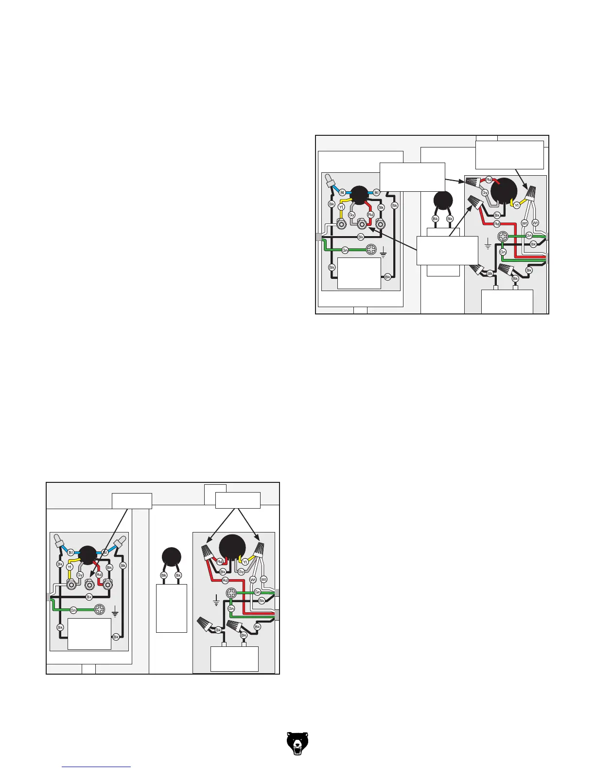
3. Open the main and coolant motor junction
boxes, remove the wire nuts on the main
motor, and loosen the terminal nut on the
coolant motor, as indicated in Figure 4.
Main Motor
Coolant Motor
HY29H
Power Switch
(Viewed From Behind)
HY29H
Coolant Switch
(Viewed From Behind)
Start
Capacitor
400 MF
125 VAC
KUOYUH
Circuit Breaker
13A 125-250V
GND
GND
Main Motor
Coolant Motor
HY29H
Power Switch
(Viewed From Behind)
HY29H
Coolant Switch
(Viewed From Behind)
Start
Capacitor
400 MF
125 VAC
KUOYUH
Circuit Breaker
13A 125-250V
GND
GND
CBB61
Run Capacitor
3MF
450VAC
CBB61
Run Capacitor
3MF
450VAC
Hot
Hot
Ground
6-15 Plug
(As Recommended)
220
VAC
G
220V Wiring Diagram
110V Wiring Diagram
110 VAC
5-15 Plug
Hot
Neutral
Ground
Loosen
Figure 4. Location of components to be removed
and loosened.
Remove
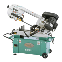
4. Connect the main motor wires, as shown in
Figure 5, with wire nuts. Once snug, wrap
electrical tape around each wire nut and the
connected wires, to reduce the likelihood
of the wire nut vibrating loose during motor
operation.
5. Connect the wires on the coolant motor as
shown in Figure 5 at the center terminal nut.
6. Close and secure the motor junction boxes.
7. Install a 6-15 plug on the end of the cord,
according to the instructions and wiring dia-
grams provided by the plug manufacturer.
—If the plug manufacturer did not include
instructions, the wiring of a generic NEMA
6-15 plug is illustrated in the Wiring sec-
tion on Page 48.
Main Motor
Coolant Motor
HY29H
Power Switch
(Viewed From Behind)
HY29H
Coolant Switch
(Viewed From Behind)
Start
Capacitor
400 MF
125 VAC
KUOYUH
Circuit Breaker
13A 125-250V
GND
GND
Main Motor
Coolant Motor
HY29H
Power Switch
(Viewed From Behind)
HY29H
Coolant Switch
(Viewed From Behind)
Start
Capacitor
400 MF
125 VAC
KUOYUH
Circuit Breaker
13A 125-250V
GND
GND
CBB61
Run Capacitor
3MF
450VAC
CBB61
Run Capacitor
3MF
450VAC
Hot
Hot
Ground
6-15 Plug
(As Recommended)
220
VAC
G
220V Wiring Diagram
110V Wiring Diagram
110 VAC
5-15 Plug
Hot
Neutral
Ground
Figure 5. Motor wires repositioned for 220V.
Re-Connect
and Tighten
Connect
and Tighten
Re-Connect
and Tighten
 Loading...