Model G0817 (Mfd. Since 05/16)
-23-
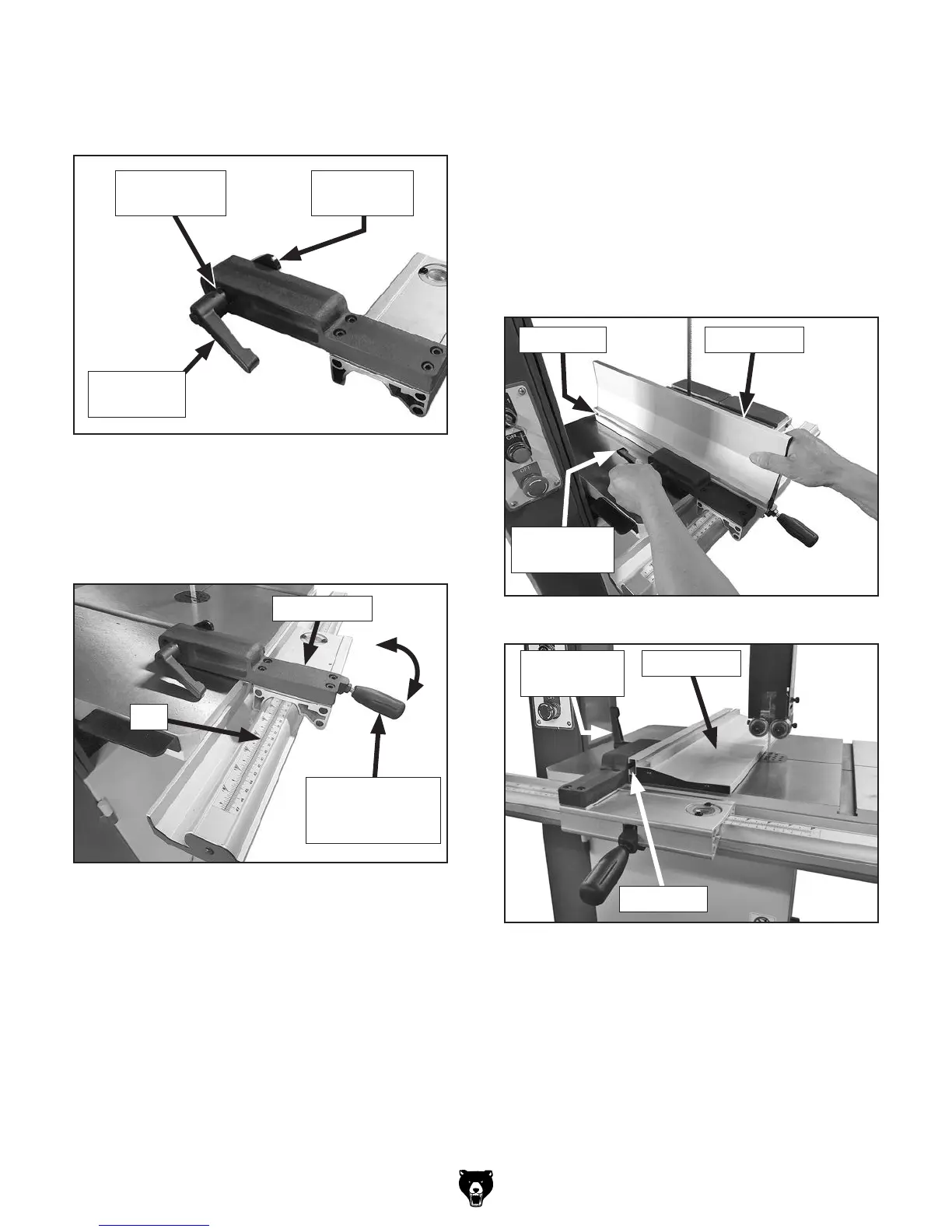
11. Place fence base on fence rail with lock lever
raised up. Push lock lever down to secure
fence in place (see Figure 32).
Figure 32. Fence base installed on fence rail.
Fence Base
Lock Lever in
Down (Locked)
Position
Rail
12. Mount fence face to fence base, sliding
T-channel (see Figures 33–34) around fence
base guide plate (see Figure 31).
— For normal workpieces, mount fence in
vertical position, as shown in Figure 33,
then rotate fence base lock lever to secure.
— For thin workpieces, mount fence in hori-
zontal position, as shown in Figure 34,
then rotate fence base lock lever to secure.
10. Install adjustable handle onto fence base with
(1) 8mm flat washer, and thread into fence
base guide plate (see Figure 31).
Figure 31. Fence base adjustable handle and
guide plate installed.
Fence Base
Guide Plate
Flat Washer
8mm
Adjustable
Handle
Figure 33. Installing fence in vertical position.
Fence Face
Lock Lever
Fence FaceT-Channel
Figure 34. Fence installed in horizontal position.
Fence Face
Lock Lever
Fence Face
T-Channel
 Loading...