Model G0817 (Mfd. Since 05/16)
-67-
2. DISCONNECT MACHINE FROM POWER!
3. Remove blade (refer to Changing Blade on
Page 46), remove table, then re-install and
properly tension blade (refer to Tensioning
Blade beginning on Page 28).
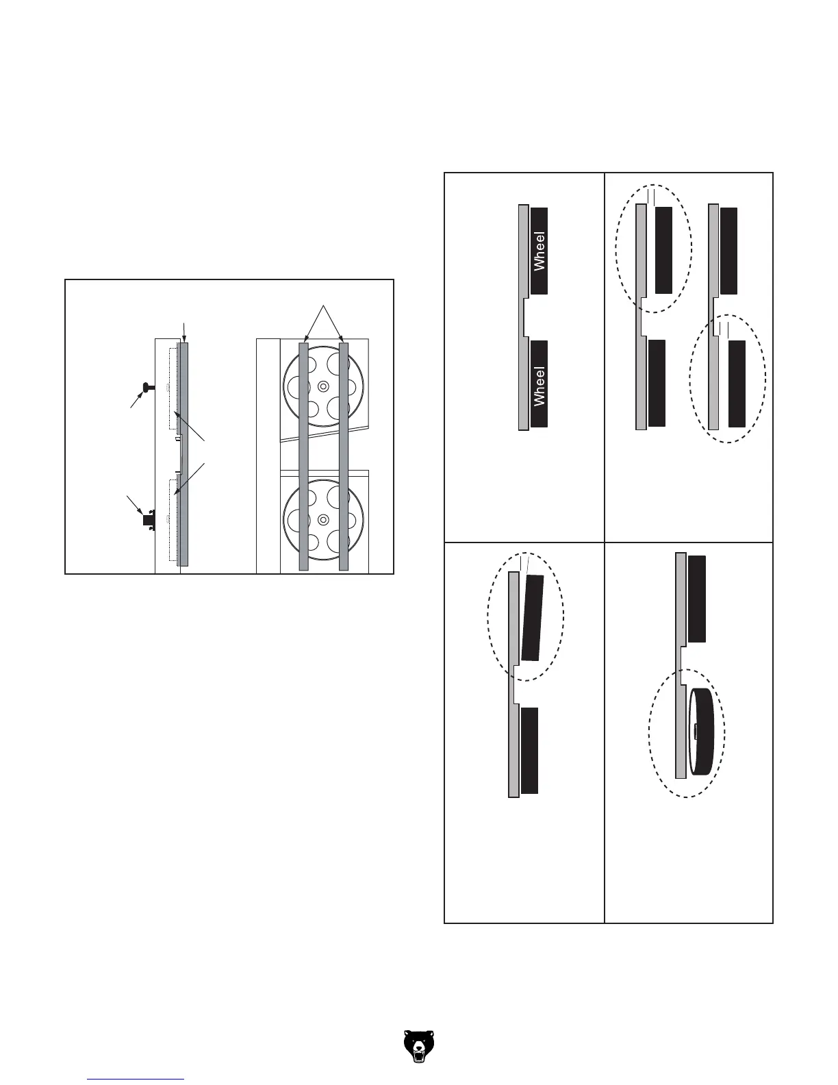
4. Place coplanarity gauge up against both
wheels in positions shown in Figure 107.
Make sure gauge fully extends across rims of
both wheels.
5. Check wheel alignment and adjust tracking
knob to bring both wheels into alignment as
much as possible. If wheels cannot be adjust-
ed coplanar, use Figure 108 to determine
how to proceed with alignment adjustments.
or
Wheels parallel and
aligned: No adjust-
ment needed.
Wheels parallel, but
not coplanar with
each other: Shim
upper or lower wheel
out.
Upper wheel not
vertically aligned with
lower wheel: Use
blade tracking knob
to tilt upper wheel.
Lower wheel not
laterally aligned with
upper wheel: Adjust
rear adjustment set
bolts to tilt lower
wheel left/right.
Coplanarity Gauge
Figure 108. Wheel alignment illustration with
solutions to misalignment problems.
Coplanarity
Gauge
Gauge Positions
Tracking
Knob
Adjustment
Hub
Wheels
Figure 107. Illustration of using coplanarity
gauge to check wheel alignment.
 Loading...