6.2 Connection On DC Side
•Before electrical connection, please ensure the inverter DC switch is at
"OFF” also disconnect AC switch, otherwise the high voltage from inverter
may cause life risk.
•Only trained authorized electrical technician can do the electric connection
also please follow the connection procedures in this manual along with local
country's regulations.
•High voltage may cause electric shocks and serious injury please do not
touch the inverter.
•Do not place flammable or explosive materials around the inverter.
•Each string's maximum open circuit voltage cannot exceed 1100Vdc, other-
wise it could lead to fire or damage the inverter. If the inverter was damaged
by higher maximum open circuit voltage (higher than 1100Vdc) product
warranty will be forfeited and Growatt will not take any responsibility.
•The inverter shall be used with IEC 61730 Class A rating PV module.
•When the group is suspended, be sure to use dust plugs to block up to
prevent entering the water into the dust.
Notice: The sunlight will generate voltage on the solar panels, after serial connection,
the high voltage may injure personnel, so before connect DC input cable you need cover
solar panels with light-tight materials and make sure the inverter DC switch is at "OFF”
status, otherwise high voltage may injure personnel.
1>Each string solar panels should be same brand and same model.
2>Under any circumstance, the maximum short circuit current should not exceed 32A.
3>The total panels power should not exceed 1.25 times of inverter input power.
4>To optimize system settings, recommend two strings with same amount solar panels.
Notice: Connectors need to be fit with male and female terminals, before connecting
panels with inverter please make sure the positive pole and negative pole, namely the
solar panels'positve pole connect to”+” negative pole connect to”-”.
Fig 6.5
6>Connect the positive and negative poles to inverter terminals, different inverter's
maximum single string input current please refer to following table.
Max. single string input current
7>Cable specifications:
19
WARNING
DANGER
Notice:1.Under any circumstance, the total current of all strings cannot exceed the
inverter's maximum current.
2. Do not touch any working solar panels.
3. Make sure the cable is unbroken.
6.3 Connection Of Communication Cables
6.3.1 RS485 port
RS485 can be used for single inverter communication also can be used for multiple
inverters(Maximum 32 inverters) , the longest distance is 500 meters, high speed (Baud
rate 38400) , the communication port as following.
485 can be used for single inverter communication also can be used for multiple
inverters(Maximum 32 inverters) , the longest distance is 500 meters, high speed (Baud
rate 38400) , the communication port as following.
It is recommended to use shielded twisted pair for RS485 cable. When a single inverter
communicates, the shielding layer of the RS485 cable needs to be connected to the
ground and can be connected to the PE of the inverter case; When multiple inverters are
connected in parallel, both RS485 interfaces must be used. The shield of the RS485 cable
should be connected to the GND of the RS485 terminal, and then the GND of all
inverters should be shorted together by wire. Finally, Connect the communication
ground GND of the inverter that is last connected to the monitoring device to the
protective ground of the inverter housing.
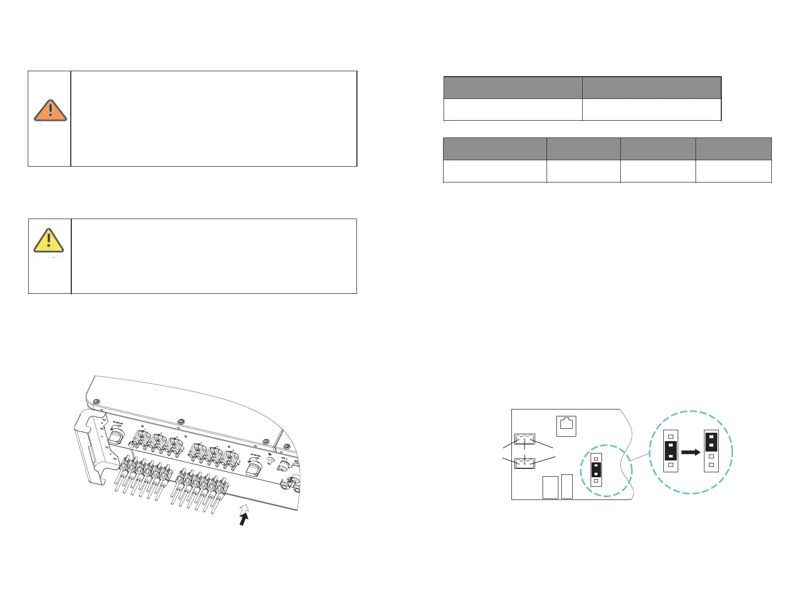
5>Decide the length of peeling base on cable terminal, use the wire stripper to connect
cable and terminal, and separately connect to specific connector.
20
Fig 6.6A
RS485 port 1
RS485 port 2
485A
485B
GND
1 2 3 4
C
N 5
Fig 6.6B
Notice: When multiple inverters are connected in parallel or the transmission distance
is long, it is recommended to change the jumper cap of CN5 pin header on the
Connector Board of the last inverter from the default 2/3 pin to 3/4 pin (As shown in
Fig6.6B). The reason for this is to increase the matching resistance.

 Loading...