29
30
8.1 Remote Data Monitoring
8.1.1 Mobile phone APP(ShinePhone) remote monitoring
MAX series inverter remote monitoring ways include APP(ShinePhone) and server Web
page, RS485,GPRS,4G,PLC(reserved) can satisfy both ways of monitoring.
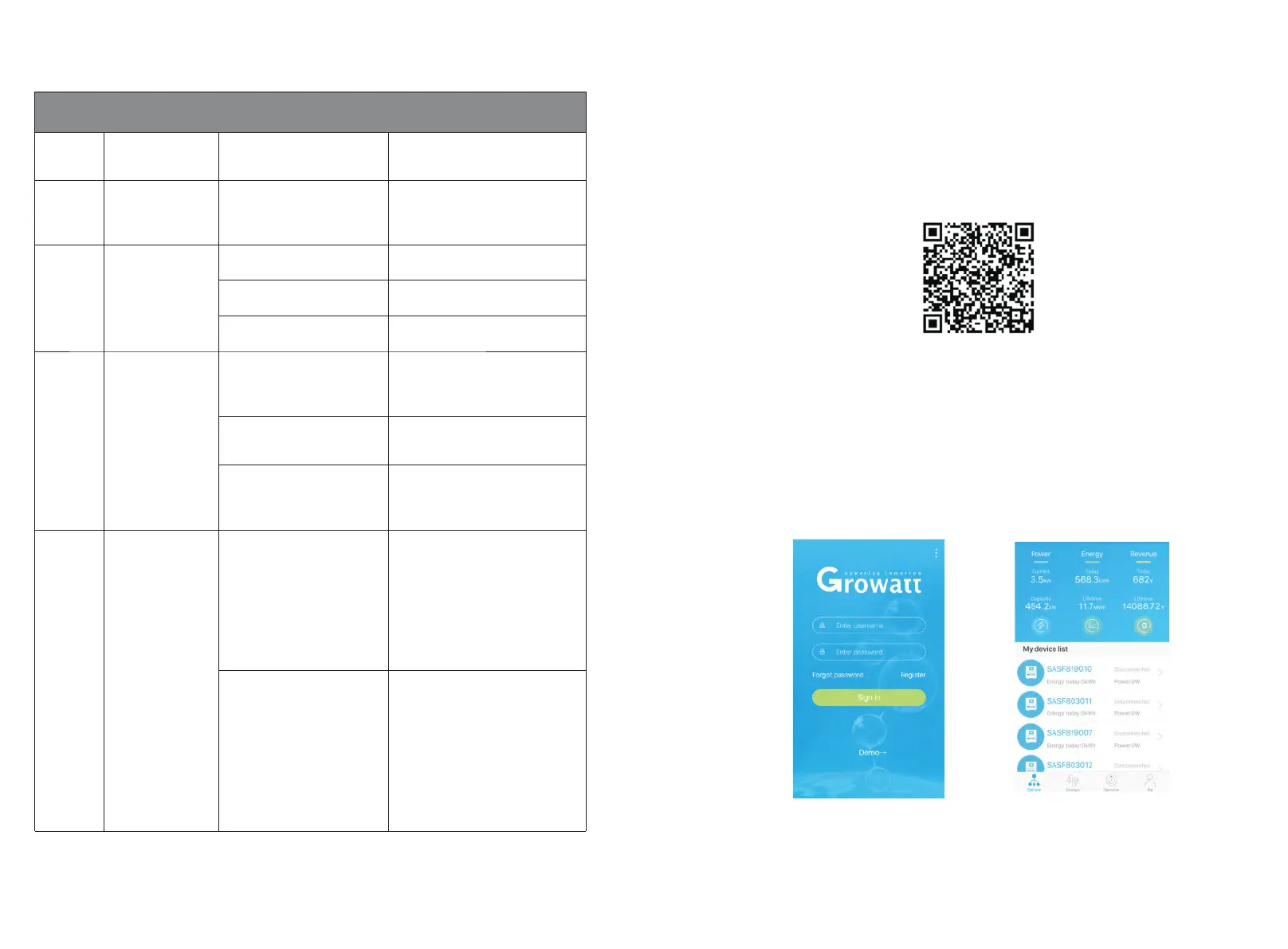
1>Scan the following QR code, or download from Android store or App store by searching
“Shinephone”, download and install software.
Note: 1.Make you it's the latest version.
2.Please find more details on http://server.growatt.com.
2>Users can register their mobile APP account by following the steps below:
Run ShinePhone, go to login page, click "register”.Registration is required to fill in the
information, with the * is required, the agreement is mandatory, you can log in to the
main interface of ShinePhone after registration, the registration page and the main
interface are as shown below.
Fig 8.1
Shinephone login and main page:
Monitoring 8
Fig 8.2
Fig 8.3
Description of LED status
AC voltage
indicator light
With AC voltage,
inverter is in a fault state
T h e gr e e n li g h t fl a s h e s
slowly, and the alarm or fault
indicator light is steady red.
Alarm or fault
indicator light
Inverter is in alarm state
Inverter is in fault state
Communication
indicator light
Inverter has external
communication, such as
RS485, GPRS, etc.
Inverter has no external
communication
Inverter upgrade or USB
interface is reading and
writing data
Power or fault
code indicator
light
Inverter is in the grid
state
The eight LEDs from left to
right represent the power of
the inverter: if 8 green lights
are on, it represents 100% of
the inverter power. As shown
in Figure 7.3, it represents
37.5% of the inverter power,
and so on.
Inverter is in fault state
The five LEDs from right to
left represent 1, 2, 4, 8, 16 in
turn, representing the fault
code o f the inv e r t er. A s
shown in Figure 7.4, the LED
status represents 2, and then
2 is added to the specific 99
to get 101, so it can be
k n o w n t h a t th e i n v e r t e r
reported error 101.

 Loading...