3.4 Operating Principle
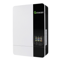
3.4.1 Operating Principle of WIT 50-100K-A-US
1> Convert DC power into AC power consistent with the voltage and power quality requirements
of the utility grid through an inverter circuit to supply power to the loads and feed power into the
grid;
2> Convert AC power into DC power through a rectifying circuit to charge the battery.
Fig 3.8 WIT 50-100K-A-US Grid-connected conceptual diagram
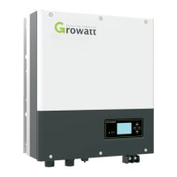
3.4.2 Operating Principle of WIT 50-100K-H-US
1> The hybrid inverter receives DC inputs form the PV strings which go through the MPPT
routes. The DC power is then converted to AC power through an inverter circuit to power the
loads and feed power into the grid;
2> The PV strings can put out power to charge the battery through the MPPT routes;
3> Convert battery power to AC power supplies for the loads and feeding to the grid;
4> Charge the battery from the grid through a rectifier circuit.
NOTE: WIT 50K-H-US models have 7 MPPT routes. WIT 63K-H models have 8 MPPT routes. WIT 75K-H and
WIT 100K-H models have 10 MPPT routes.
Fig 3.9 WIT 50-100K-H-US Grid-connected conceptual diagram
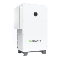
3.4.3 Operating Principle of WIT 50-100K-AE-US and WIT 50-100K-AU-US
1> Convert battery power to AC power to power the loads and export energy to the grid;
 Loading...

