13
7.7 External start/stop
The pump can be started or stopped via an external
potential-free contact or a relay connected to
terminals 7 and 8, see section 5.2 Connection
diagram.
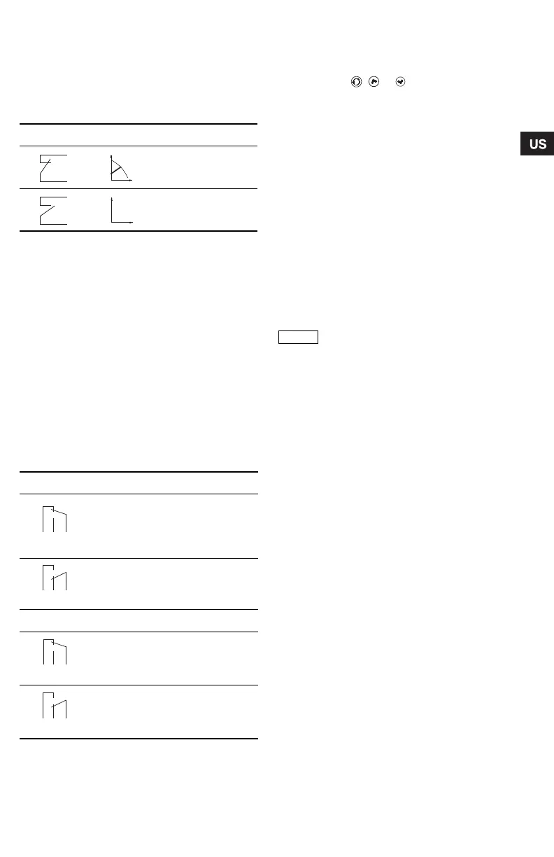
Functional diagram: Start/stop input
7.8 Signal relay
The pump incorporates a signal relay, terminals
1, 2 and 3, for a potential-free fault and operating
signal. The function of the signal relay, fault signal
(factory setting) or operating signal, is set with the
R100.
The output, terminals 1, 2 and 3, is electrically
separated from the rest of the controller.
The signal relay is activated as follows:
• Fault signal
The signal relay is activated together with the
red indicator light on the pump, see section
8.2 Control panel.
• Operating signal
The signal relay is activated together with the
green indicator light on the pump, see section
8.2 Control panel.
Functions of signal relay
Resetting of fault indications
A fault indication can be reset in one of the following
ways:
• Briefly press , or on the pump. This will
not influence the pump performance set.
• Briefly switch off the electricity supply to the
pump.
• With the R100, see section 8.4 R100 display
overview.
Before the pump can revert to normal duty, the fault
cause must be eliminated.
If the fault disappears by itself, the fault indication
will automatically be reset.
The fault cause will be stored in the pump alarm log.
The latest five faults can be called up with the R100.
7.9 Indicator lights
For position on pump, see fig. 13, section 8.2 Control
panel.
The indicator lights, pos. 2, are used for operating
and fault indication. Furthermore, they indicate
whether the pump is externally controlled.
The function of the operating and fault indicator
lights can be found in section 9. Fault finding chart.
The indicator light for external control is on
• if the pump control panel is inactive,
• if the pump is in constant-curve operating mode,
• if the temperature influence is active or
• if the pump is controlled by an external unit.
Start/stop input
Normal duty
Stop
Signal relay Fault signal
Not activated:
• The electricity supply has been
switched off.
• The pump has not registered
afault.
Activated:
• The pump has registered a fault.
Signal relay Operating signal
Not activated:
• The pump has been set to stop.
• The pump has registered a fault
and is unable to run.
Activated:
• The pump is running.
• The pump has registered a fault,
but is able to run.
When the R100 remote control
communicates with the pump, the red
indicator light will flash rapidly.
Grundfos.bk Page 13 Friday, January 15, 2010 3:23 PM
 Loading...