15
8.2 Control panel
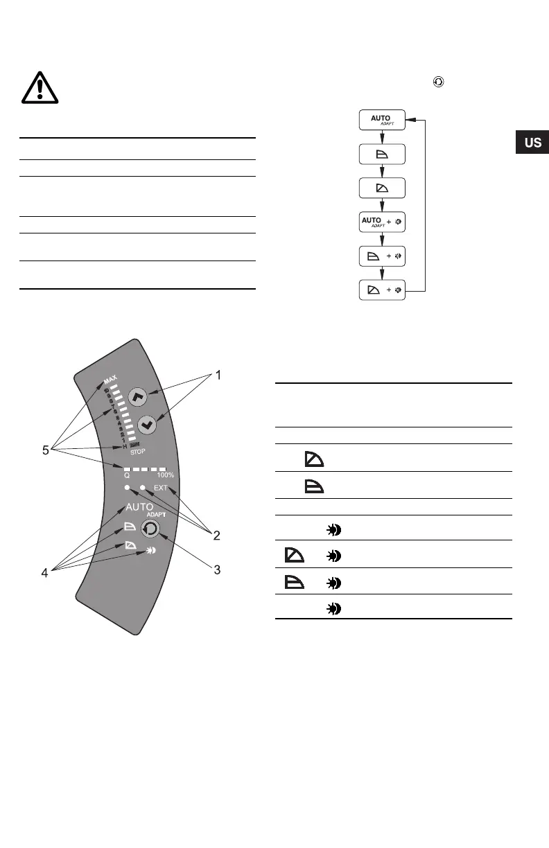
The control panel, fig. 13, incorporates:
For further information, see section 9. Fault finding
chart.
Fig. 13 Control panel
8.2.1 Control mode setting
Description of function, see section 7.1 Control
modes.
To change the control mode, press , pos. 3,
according to this cycle:
Fig. 14 Cycle of control modes
Automatic night-time duty can be activated together
with each of the control modes.
The light symbols in pos. 4, see fig. 13, indicate the
pump settings:
"–" = no light.
WARNING!
At high liquid temperatures, the pump
may be scalding hot, only the buttons
should be touched to avoid burns.
Pos. Description
1 Buttons for setting
2
• Indicator lights for operating and fault
indication and
• symbol for indication of external control
3 Button for change of control mode
4
Light symbols for indication of control
mode and night-time duty
5
Light fields for indication of head, flow and
operating mode
TM03 8798 2507
TM03 1288 1505
Light in Control mode
Automatic
night-time
duty
AUTO
ADAPT AUTOADAPT NO
Proportional
pressure
NO
Constant pressure NO
– Constant curve NO
AUTO
ADAPT
AUTOADAPT YES
Proportional
pressure
YES
Constant pressure YES
– Constant curve YES
Grundfos.bk Page 15 Friday, January 15, 2010 3:23 PM
 Loading...