English (GB)
55
14.3 CIM/CIU 500
You can detect faults in CIU 500 by observing the status of the
two communication LEDs. See the table below and section
4.4 CIM 500 Modbus TCP.
14.3.1 LED status
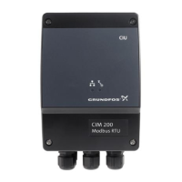
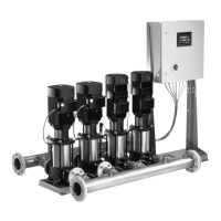
CIU 500 fitted in a Grundfos booster system
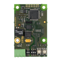
CIM 500 fitted in CIU 500
14.3.2 CIM/CIU 500 Modbus TCP communication faults
Fault (LED status) Possible cause Remedy
1. LED1 and LED2 remain off when the
power supply is connected.
a) CIM 500 is fitted incorrectly in the
Grundfos product.
Check that CIM 500 is fitted and connected
correctly.
b) CIM 500 is defective. Replace CIM 500.
2. The LED2 for internal communication is
flashing red.
a) No internal communication between
CIM 500 and the Grundfos product.
Check that CIM 500 is fitted correctly in the
Grundfos product.
3. The LED2 for internal communication is
permanently red.
a) CIM 500 does not support the Grundfos
product connected.
Contact the nearest Grundfos company.
4. The Modbus LED1 is permanently red. a) Fault in the CIM 500 Modbus TCP
configuration.
Check that the rotary switch SW1 is set to 1.
Check that the Modbus TCP/IP address
configuration is correct.
See section A.4 Modbus TCP configuration
on page 62.
5. LED1 is permanently red and green at
the same time.
a) Error in firmware download. Use the webserver to download the
firmware again.
6. LED2 is permanently red and green at
the same time.
a) Memory fault. Replace CIM 500.
Fault (LED status) Possible cause Remedy
1. LED1 and LED2 remain off when the
power supply is connected.
a) CIU 500 is defective. Replace CIU 500.
2. The LED2 for internal communication is
flashing red.
a) No internal communication between
CIU 500 and the Grundfos product.
• Check the cable connection between the
Grundfos product and CIU 500.
• Check that the individual conductors
have been fitted correctly, for example
not reversed.
• Check the power supply to the Grundfos
product.
3. The LED2 for internal communication is
permanently red.
a) CIM 500 does not support the Grundfos
product connected.
Contact the nearest Grundfos company.
4. The Ethernet LED1 is permanently red. a) Fault in the CIM 500 Modbus TCP
configuration.
Check that the rotary switch SW1 is set to 1.
Check that the Modbus TCP/IP address
configuration is correct. See section
A.4 Modbus TCP configuration on page 62.
5. LED1 is permanently red and green at
the same time.
a) Error in firmware download. Use the webserver to download the
firmware again.
6. LED2 is permanently red and green at
the same time.
a) Memory fault. Replace CIM 500.
Fault Possible cause Remedy
1. The slave does not respond to
telegrams.
a) Configuration or wiring error. • Check the visual diagnostics on the
Modbus slave. Normal conditions are
that the Grundfos GENIbus LED2 is
permanently green and that the Modbus
TCP LED1 is off or flashing green. If this
is not fulfilled, see section 14.3.1 LED
status.
• Ensure that the cable between the
Modbus TCP master and the Modbus
slave is connected correctly.
See section 7.1 Connecting the Ethernet
cable.
• Ensure that the slave IP address is
configured correctly, and that the correct
slave IP address is used in the Modbus
master poll. See section 7.3 Setting the
IP addresses.

 Loading...


