Functions
16
SMART Digital S
3
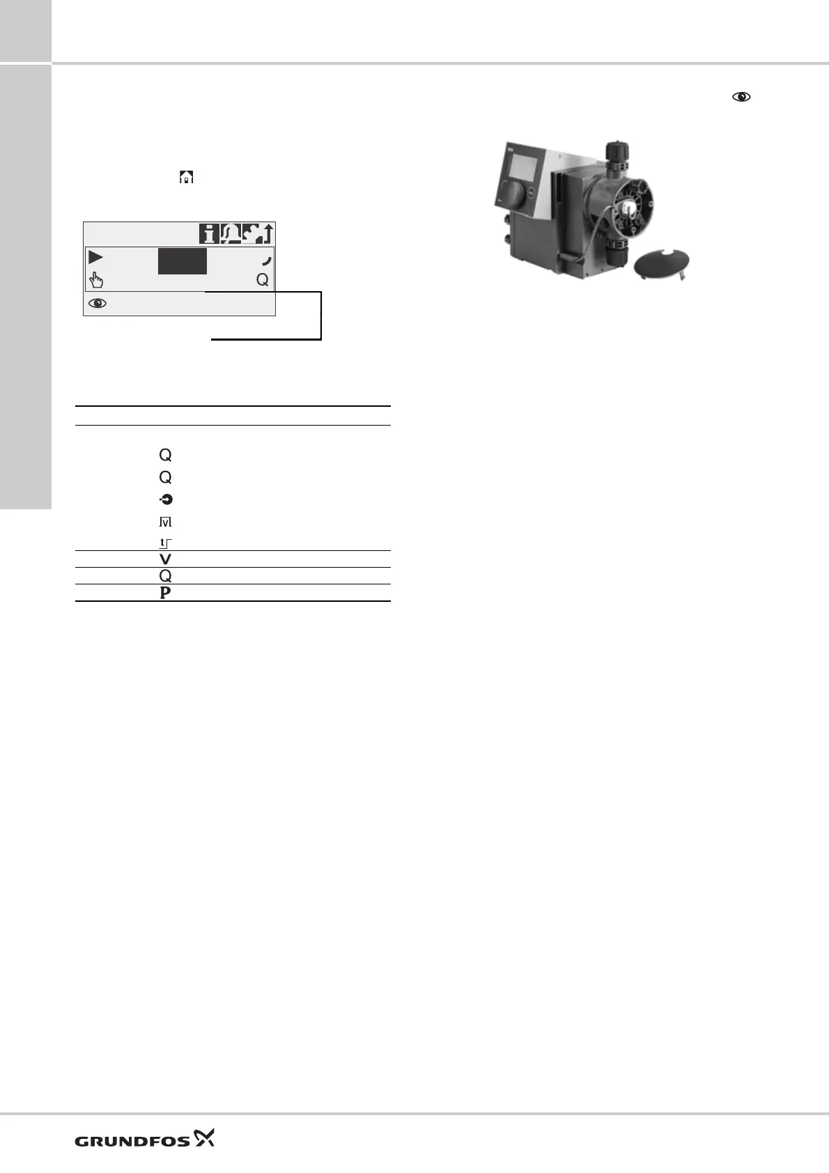
Additional display
Applies to DDA, DDC
The additional display function provides further useful
status information, e.g. the target flow rate as well as
the actual flow rate. The value is shown in the
operation display together with the corresponding
symbol.
Fig. 16 Additional display
The following additional information can be selected:
1) Only DDA-FCM control variant
2) Only DDA-FCM/FC control variant
3) Only DDA pumps
4) Only DDA pumps and DDC-AR control variant
FlowControl
Applies to DDA-FC/FCM
Fig. 17 DDA FlowControl
The pump monitors the dosing process of liquids when
the FlowControl function is activated. Although the
pump is still operating, some influences such as air
bubbles may cause reduced flow rates or even stop
the dosing process. For optimal process safety and
reliability, the activated FlowControl function
immediately detects and displays the following
malfunctions:
• Overpressure
• Discharge line burst
• Air bubbles in the dosing head
• Cavitation at the suction side
• Suction valve leakage
• Discharge valve leakage.
The unique FlowControl is based on an intelligent and
maintenance-free sensor integrated in the dosing
head. During the dosing process, the sensor measures
the actual pressure and sends the measured value to
the microprocessor in the pump. An internal indicator
diagram is generated combining the actual pressure
value with the diaphragm position (stroke length).
With it, the dosing process is monitored, as the
different malfunctions can immediately be detected
due to their specific deviations in the curve.
Compressible air bubbles, for instance, will reduce the
discharge phase and the stroke volume (see fig. 18).
The sensitivity and the delay of the FlowControl
function can be adjusted individually.
FlowControl requires a minimum backpressure of
2 bar. Grundfos recommend an additional
spring-loaded valve (approx. 3 bar) on the discharge
side for dosing low capacities (< 1 l/h) (please see
page 46).
TM04 1633 1810
Settings Description
Default display
Depending on the operation mode:
Actual flow (manual, pulse)
1)
Target flow (pulse)
Input current (analog)
4)
Remaining batch volume (batch, timer)
3)
Time until next batch (timer)
3)
Dosed volume
Total dosed volume (Counters see page 13)
Actual flow
Actually measured flow
1)
Backpressure
Current backpressure in the dosing head
2)
7.49 l/h
Manual
7.50
l/h
Operation
TM04 1641 2617
 Loading...