Functions
9
SMART Digital S
3
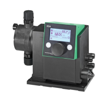
Control cube DDA and DDC
DDA and DDC pumps are supplied with front-mounted
control cube. The position of the control cube can
easily be changed by unfastening 2 screws, lifting the
cube, turning it to the left or to the right and fastening
both screws again.
Fig. 6 Two of three possible control cube positions
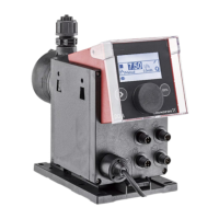
Operating elements DDA and DDC
Fig. 7 Operating elements DDA and DDC
The click wheel guides the user quickly and easily
through the plain-text menu.
If the maximum capacity is required over a short period
of time, for example during start-up, press the 100 %
key. To set the pump to run for a specific number of
seconds at maximum capacity, press the 100 % key
and turn the click wheel clockwise simultaneously.
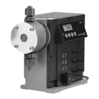
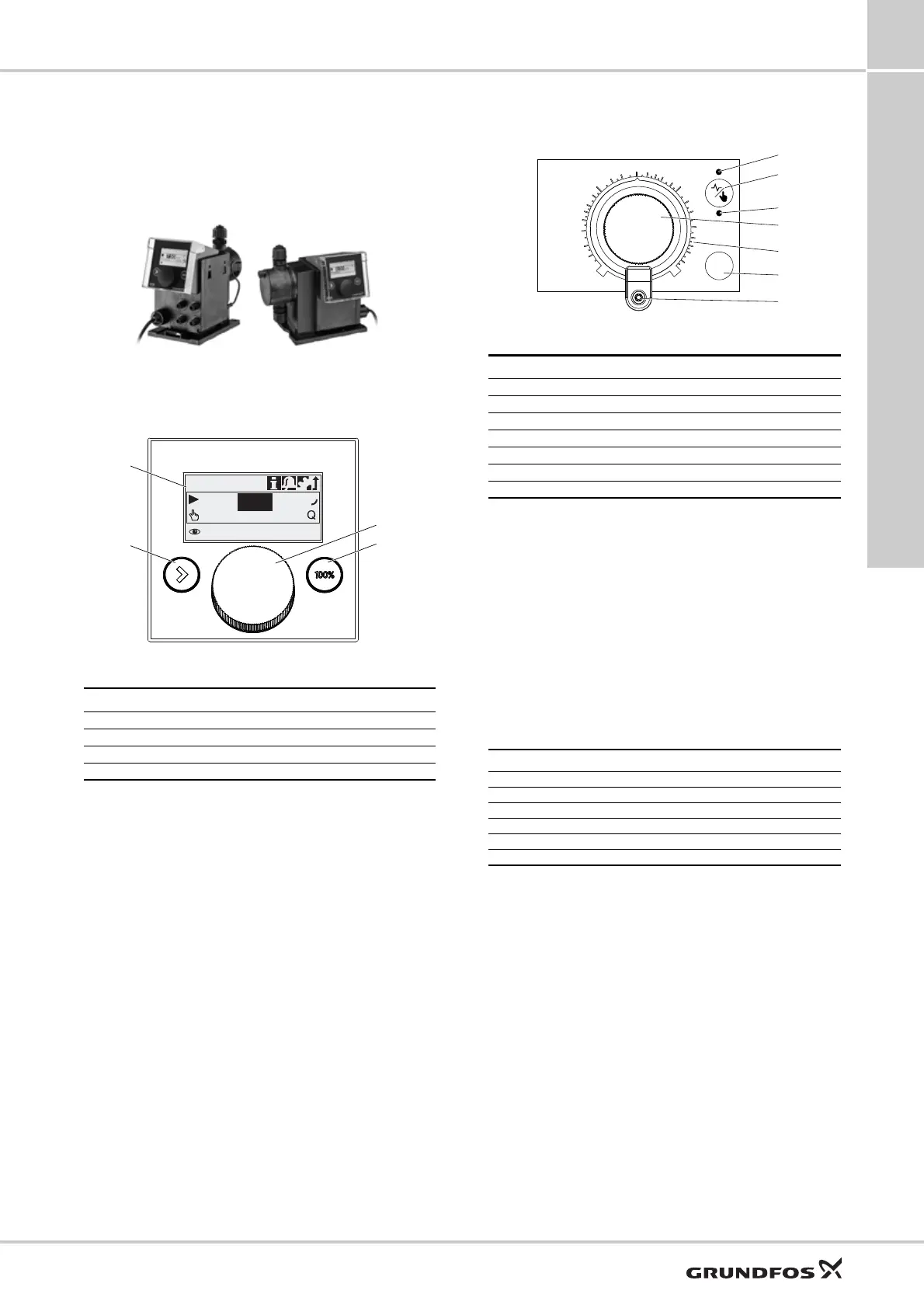
Operating elements DDE
Fig. 8 Operating elements DDE
With the capacity adjustment knob the capacity of the
pump can easily be adjusted in % of the maximum
flow.
Applies to DDE-PR, DDE-P
When holding down the operation mode switch, the
pump changes from manual operation to pulse mode
or vice versa.
If the maximum capacity is required over a short period
of time, for example during start-up, press the 100 %
key.
Depending on the selected operation mode, the
respective status LED (pulse or manual) is activated
according to the following table:
TM06 9584 2517TM06 8989 1517
Pos. Description
1 Graphical LC display
2 [Start/Stop] key
3 Click wheel
4 [100%] key
7.49 l/h
Manual
7.5
l/h
Operation
1
2
3
4
TM04 1596 1817
Pos. Description
1 Status LED pulse (DDE-PR and DDE-P)
2 Operation mode switch (DDE-PR and DDE-P)
3 Status LED manual
4 Capacity adjustment knob
5 Logarithmic scale
6 100 % key (DDE-PR and DDE-P)
7 Mechanical lock
LED colour Pump status
Green (flashing) Stopped
Green Running
Red-green (flashing) External stop
Yellow Low level (warning)
Red Empty tank (alarm)
Red (flashing) Motor blocked (alarm)
100%
0%
0.15
0.2
0.3
0.4
0.5
0.6
0.8
1.5
2
3
4
5
6
8
15
20
30
40
50
60
80
10
1

 Loading...