Functions
21
SMART Digital S
3
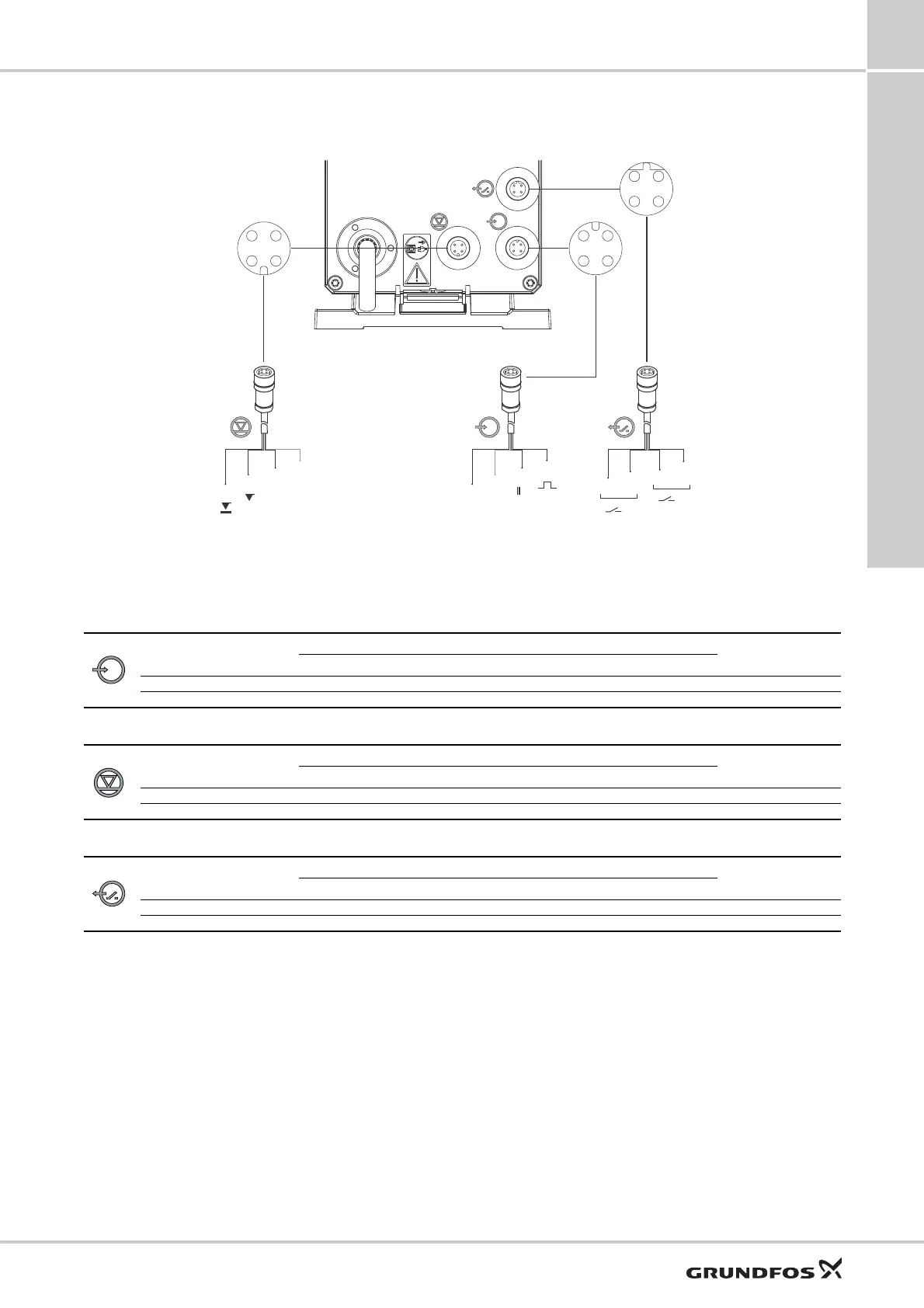
Wiring diagram, DDE-PR, -P
Cable 1: External stop and pulse input
Cable 2: Level input
Cable 4: Relay output*
* applies to DDE-PR
TM04 1597 0312
1
3
4
2
3
4
1
2
1
3
Ź
2
1
GND
GND
12
34
34
12
12
34
Cable 2
Level input
see page 39, suction
lances
Cable 1
External stop/pulse
Product No.
2 m cable: 96609014
5 m cable: 96609016
Cable 4
Relay output
Product No.
2 m cable: 96609017
5 m cable: 96609019
Function
Pin holes
Plug type
1/brown 2/white 3/blue 4/black
External stop GND X Contact
Pulse GND X Contact
Function
Pin holes
Plug type
1234
Low level X GND Contact
Empty tank X GND Contact
Function
Pin holes
Plug type
1/brown 2/white 3/blue 4/black
Relay 1 (Alarm) X X Contact
Relay 2 (see page 14) X X Contact

 Loading...